Experiment 1
The first experimental design tool test.
Introduction
My initial plan in an ideal scenario would have been this:
- figure out what sensor I need to determine 2 dimensional position (position sensor)
- make a simple circuit with a switch (on/off button) that records the x and y coördinates
- write processing code (or another language) that uses this x and y data to draw dots/lines (dots together form the line) when the button is pressed
- add a sensor with an analogue output that records the loudness of surrounding noise
- connect that value to the width/scatter of the dot (“brush”) > use increments so the line will be less bumpy
- make different (scatter) brushes in processing
- add buttons for different brushes
But this went south during the first step already as apparently determining 2 dimensional position (absolute or relative) is incredibly difficult. My first experiment will therefore be to figure out how I can use the sensor data generated by an accelerometer in a Processing sketch, and if I maybe can make another experimental design tool using that. I did get the suggestion from a friend to try positioning using a camera and OpenCV so I may look into that later.
But first: the start of the accelerometer experiment.
Used sensors and items
- Accelerometer
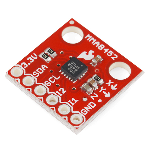
https://www.sparkfun.com/products/retired/10955 https://cdn.sparkfun.com/datasheets/Sensors/Accelerometers/MMA8452Q.pdf
| Pin Label | Pin Function | Input/Output | Notes |
|---|---|---|---|
| 3.3V | Power Supply | Input | Should be between 1.95 - 3.6V |
| SDA | I2C Data Signal | Bi-directional | Bi-directional data line. Voltage should not exceed power supply (e.g. 3.3V). |
| SCL | I2C Clock Signal | Input | Master-controlled clock signal. Voltage should not exceed power supply (e.g. 3.3V). |
| I2 | Interrupt 2 | Output | Programmable interrupt — can indicate data ready, orientation change, tap, and more. |
| I1 | Interrupt 1 | Output | Programmable interrupt — can indicate data ready, orientation change, tap, and more. |
| GND | Ground | Input | 0V/common voltage. |
- Breadboard
- Jumper wires
- Arduino Uno
- 330Ω Resistors
Goals
- To see how an accelerometer works
- To convert the x and y data to something visual using Processing and Arduino
Important
The MMA8452Q has a maximum voltage of 3.6V – that range applies to both the power supply and the I2C pins. Because I am using an Arduino (5V), some level-shifting is required between devices.
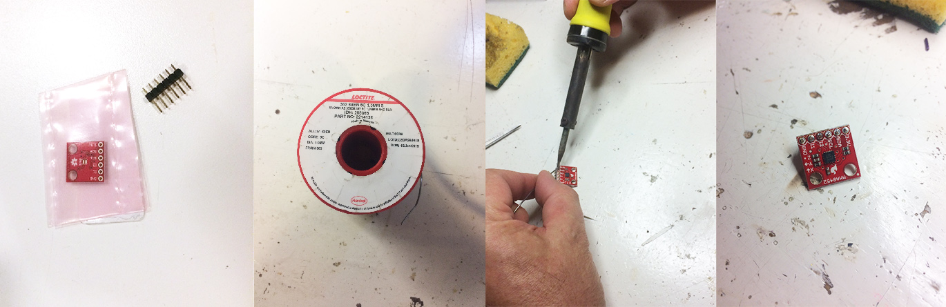
Step 1: soldering the headers to the breakout board
Make sure you follow these steps when soldering.
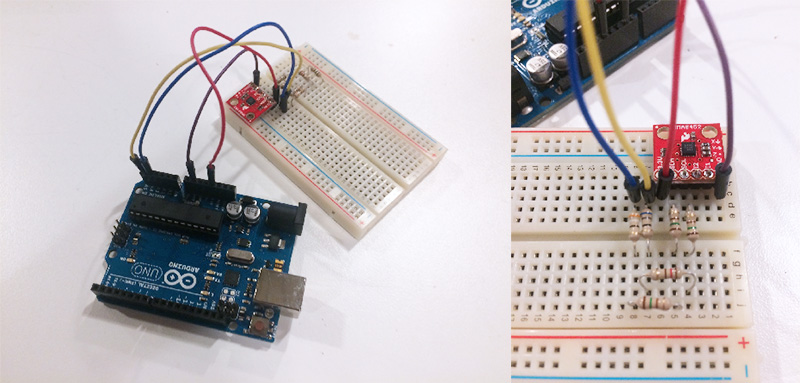
Step 2: setting up the board using the hookup guide
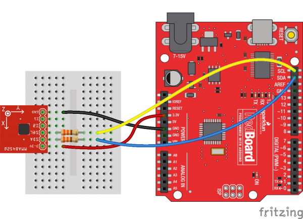
Since the MMA8452Q’s maximum voltage is 3.6V, you’ll need to do some level shifting between your Arduino and accelerometer. Powering the accelerometer off the Arduino’s 3.3V rail is a good start, but you’ll also need to add some protection on the SDA and SCL lines.
In the example hookup above, we used a pair of series resistors on the SDA and SCL lines. This version of “level shifting” works in a pinch, but, if you want a more reliable level-shifting setup, we recommend using a more robust level shifter between the boards.
- Since there were no 330 ohm resistors available I put multiple resistors in series to create the same amount of resistance. Using a multimeter I measured the following resistance: 334.1 ohm on the SCL pin and 333.6 ohm on the SDA pin.
- I’m using an Arduino Uno, on which the A4 pin corresponds with the SDA pin and the A5 pin with the SCL pin.
Step 3: test using the example code
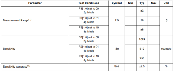
The output result from the example code can either be in raw x, y and z data, or calculated acceleration values read out of the accelerometer; these are in units of g’s.
Calculated acceleration values
Raw data
However these values are not the kind of x, y and z data that I wanted; apparently it is very hard to determine position using sensors. What I can do is use this data for other purposes in my tools (or to figure out a new way of illustrating using these values) but that will not fix my current problem.
Step 4: connecting Arduino to Processing to use the generated data
To accomplish this, I used the provided example code for the accelerometer provided by Sparkfun. I added some more comments for clarity. https://github.com/sparkfun/SparkFun_MMA8452Q_Arduino_Library/tree/master/examples/Example2_RawDataReading
Arduino code
/*
  Library for the MMA8452Q
  By: Jim Lindblom and Andrea DeVore
  SparkFun Electronics

  Do you like this library? Help support SparkFun. Buy a board!
  https://www.sparkfun.com/products/14587

  This sketch uses the SparkFun_MMA8452Q library to initialize
  the accelerometer and stream raw x, y, z, acceleration
  values from it.

  Hardware hookup:
  Arduino --------------- MMA8452Q Breakout
    3.3V  ---------------     3.3V
    GND   ---------------     GND
  SDA (A4) --\/330 Ohm\/--    SDA
  SCL (A5) --\/330 Ohm\/--    SCL

  The MMA8452Q is a 3.3V max sensor, so you'll need to do some
  level-shifting between the Arduino and the breakout. Series
  resistors on the SDA and SCL lines should do the trick.

  License: This code is public domain, but if you see me
  (or any other SparkFun employee) at the local, and you've
  found our code helpful, please buy us a round (Beerware
  license).

  Distributed as is; no warrenty given.
*/

#include <Wire.h>                 // Must include Wire library for I2C
#include "SparkFun_MMA8452Q.h"    // Click here to get the library: http://librarymanager/All#SparkFun_MMA8452Q

MMA8452Q accel;                   // Create instance of the MMA8452 class

void setup() {
  Serial.begin(9600);             // Sets the data rate in bits per second (baud) for serial data transmission.
  Serial.println("MMA8452Q Raw Data Reading Code!");
  Wire.begin();

  if (accel.begin() == false) {
    Serial.println("Not Connected. Please check connections and read the hookup guide.");
    while (1);
  }
}

void loop() {
  if (accel.available()) {      // Wait for new data from accelerometer
    // Raw of acceleration of x, y, and z directions
    Serial.print(accel.getX());
    Serial.print("\t");         // This prints a tab so you can distinguish the numbers
    Serial.print(accel.getY());
    Serial.print("\t");
    Serial.print(accel.getZ());
    Serial.println();           // New line
  }
}
Processing code
This was based on the final answer on this forum: https://processing.org/discourse/beta/num_1254511350.html. The next step would be to figure out how to separate the raw data into separate arrays.
//import Serial communication library
import processing.serial.*;

Serial myPort;  // Create object from Serial class
String myString = null;
float num;
int lf = 10;    // Linefeed in ASCII code; a linefeed means moving one line forward. The code is \n.

void setup()
{
  String portName = Serial.list()[0]; //change the 0 to a 1 or 2 etc. to match your port
  myPort = new Serial(this, portName, 9600);
}

void draw() {
  while (myPort.available() > 0) {
    myString = myPort.readStringUntil(lf);
    if (myString != null) {
  print(myString);  // Prints String but without the tabs
  num=float(myString);   // Converts and prints float, this does not work most of the time
  println(num);          // because when there is a minus in the second or third number
    }                    // it's not a number (NaN)
  }
}
The standard mode is 2g mode, so the sensitivity is 1024 counts/g.
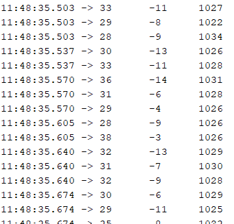
When placed flat on the floor, these are the measured values:
Step 5: Sensor data into arrays
To use the data in Processing, you have to read the entire input line from the Arduino, then split the line with a comma (then you have a String[]) and parse each number into int[] with index one to one matching.
Arduino code
#include <Wire.h>                 // Must include Wire library for I2C
#include "SparkFun_MMA8452Q.h"    // Click here to get the library: http://librarymanager/All#SparkFun_MMA8452Q

MMA8452Q accel;                   // Create instance of the MMA8452 class

void setup() {
  Serial.begin(9600);             // Sets the data rate in bits per second (baud) for serial data transmission.
  //  Serial.println("MMA8452Q Raw Data Reading Code!"); // This messes up the integer arrays
  Wire.begin();

  if (accel.begin() == false) {
    Serial.println("Not Connected. Please check connections and read the hookup guide.");
    while (1);
  }
}

void loop() {
  if (accel.available()) {      // Wait for new data from accelerometer
    // Raw of acceleration of x, y, and z directions
    Serial.print(accel.getX());
    Serial.print(",");
    Serial.print(accel.getY());
    Serial.print(",");
    Serial.print(accel.getZ());
    Serial.println();           // New line
    delay(50);                  // This delay is neccessary because Processing can't handle the speed (after a few moments it tries to combine two values into one int and that gives an error)
  }
}
Processing code
//import Serial communication library
import processing.serial.*;

Serial myPort;  // Create object from Serial class
String myString = null;
int lf = 10;    // Linefeed in ASCII code

void setup()
{
  String portName = Serial.list()[0]; //change the 0 to a 1 or 2 etc. to match your port
  myPort = new Serial(this, portName, 9600);
}

void draw() {
  while (myPort.available() > 0) {
    myString = myPort.readStringUntil(lf);
    if (myString != null) {
      //print(myString);
      String[] list = split(myString, ",");
      // printArray(list);

      int[] intList = new int[list.length];
      for (int i = 0; i < list.length; i++)
      {
        intList[i] = Integer.parseInt(list[i].trim()); // this has to be trimmed, because of
      }          // this issue: https://stackoverflow.com/questions/27604918/parseint-processing
      printArray(intList);
      println();
    }
  }
}
Step 6: Use array data to generate art
The video above was my first try at using the accelerometer values. To draw with the accelerometer, I wrote the following code underneath println() in the code above.
      pushMatrix();
      translate(300, 400);
      ellipse(intList[0], intList[1], 5, 5);
      popMatrix();
      int strokeInput = abs(intList[2]/8);
      fill(strokeInput, strokeInput, strokeInput);
This is the result after a bit of trying out:
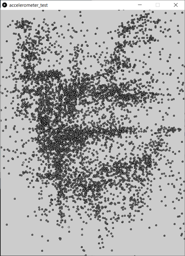
After this I worked on modifying the Processing code to make the illustration better. I also used a higher baud rate to receive more data so I would be able to make smoother lines.
Add soft sensor
steps:
- first test the wire and the fabric (conductivity) by trying to light an LED with them
- then make a kind of pressure sensor and see what the output values look like (can I use the pressure to change the color of the illustration? or should I use it as a soft on/off button?)
I made a soft sensor attached to a pen to turn an LED on and off for now, to test it out. fjiaofjiaojdij
I would rather save the digital drawings on a sd every time I press a button but for now being able to attach it to Processing should be fine.
Sources
https://learn.sparkfun.com/tutorials/connecting-arduino-to-processing/all https://learn.sparkfun.com/tutorials/mma8452q-accelerometer-breakout-hookup-guide