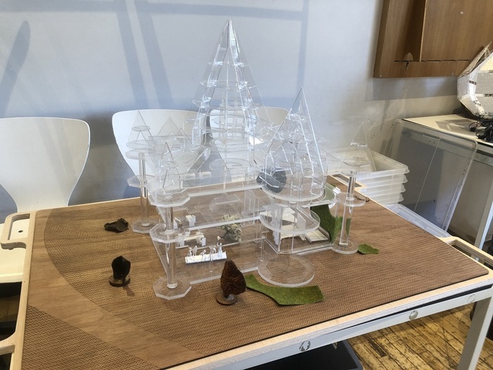
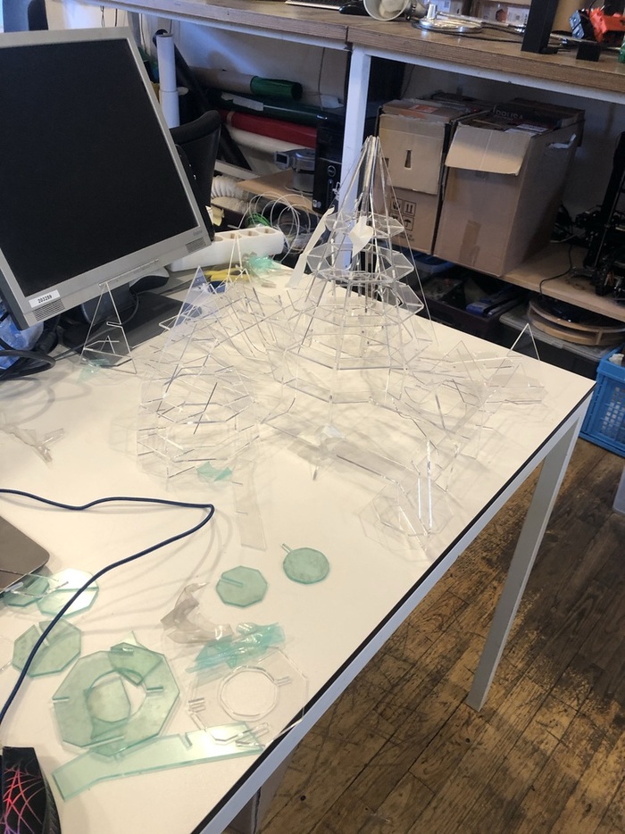
Making a model of the Waag building
Waag has been selected by the Dutch ministry for Education, culture and science as the Future Lab design & technology starting January 2021. This calls for a rethinking of the function and position of the Waag organisation and the Waag building in Amsterdam as a public space. Currently, the fablab, textile lab and wetlab are mostly hidden from view. The only way in and out is via a door hidden in plain sight in one of the towers on the side. Waag should be more visible and accessible to the people of Amsterdam; this model’s purpose is to visualize our ideas.
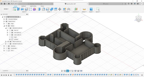
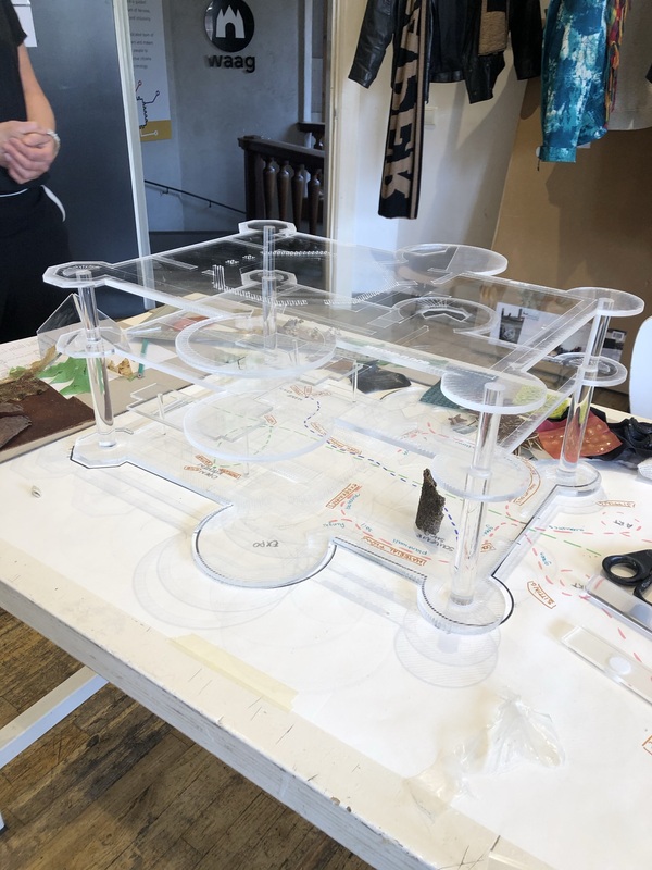
Files can be downloaded below. Exploded view of the final model including roof:
Process
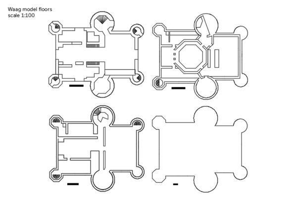
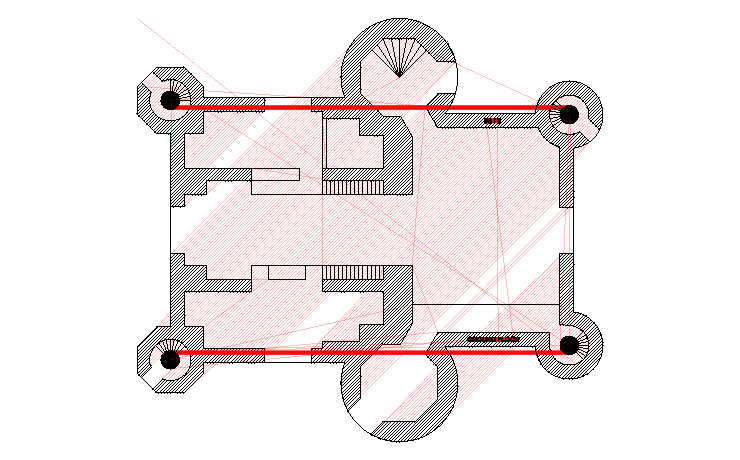
- Tracing floor plans
I started out with tracing the floor plans in Illustrator, since then I could easily trace the scanned images. Then I exported the vectors as DXF and imported them in Fusion360.
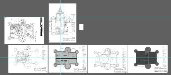
Halfway through working like this I realized that it probably would have been easier to have started in Fusion right away, since we decided to simplify the plans where we could. working with the exported Illustrator file turned into a hot mess of seemingly overlapping lines that ended up being 0,01mm apart, ‘perpendicular’ corners that were actually 89,97 degrees etc. For the physical model all of these small differences didn’t really matter as they would not be visible, but it wasn’t a great workflow.
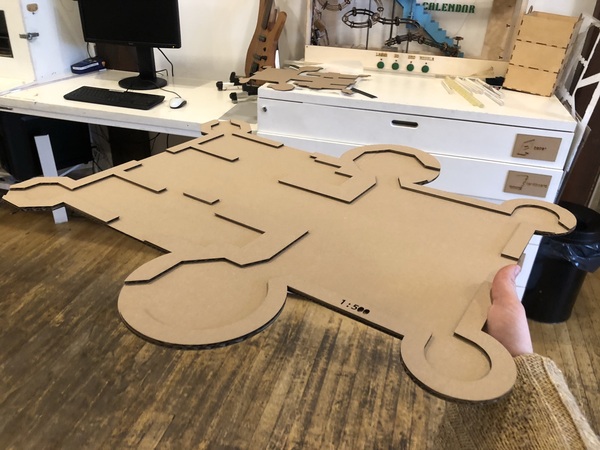
- Lasercutting first floor in cardboard
I first miscalculated and thought it was a scale 1:500 but that would make the Waag very large. It’s supposed to be 1:50. We liked the size so we continued with scale in mind.
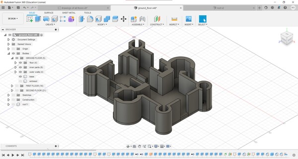
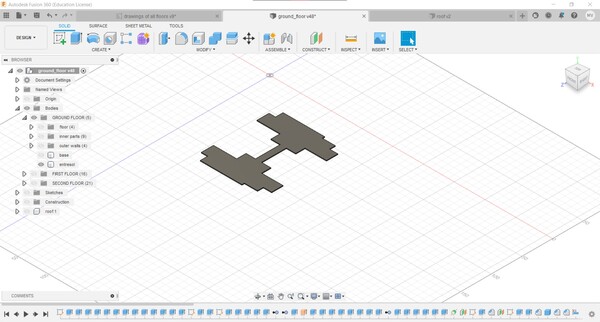
- Modeling the floors in Fusion360
Ground floor and entresol:
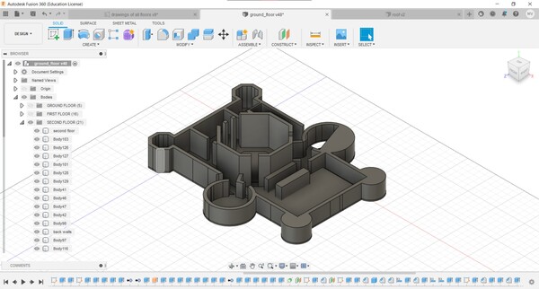
First and second floor:
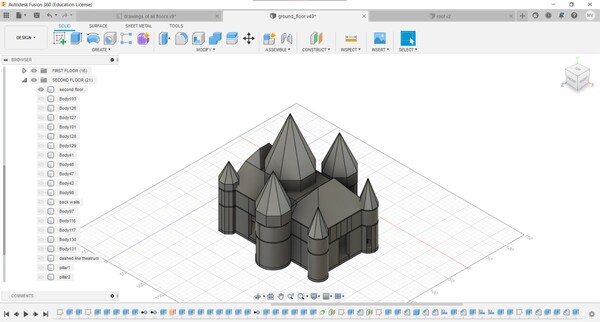
Full model:
Final floors (can be downloaded below):
Before deciding on lasercutting the floors and keeping them as open as possible, I tried out different Slicer options with a previous version of the ground floor.
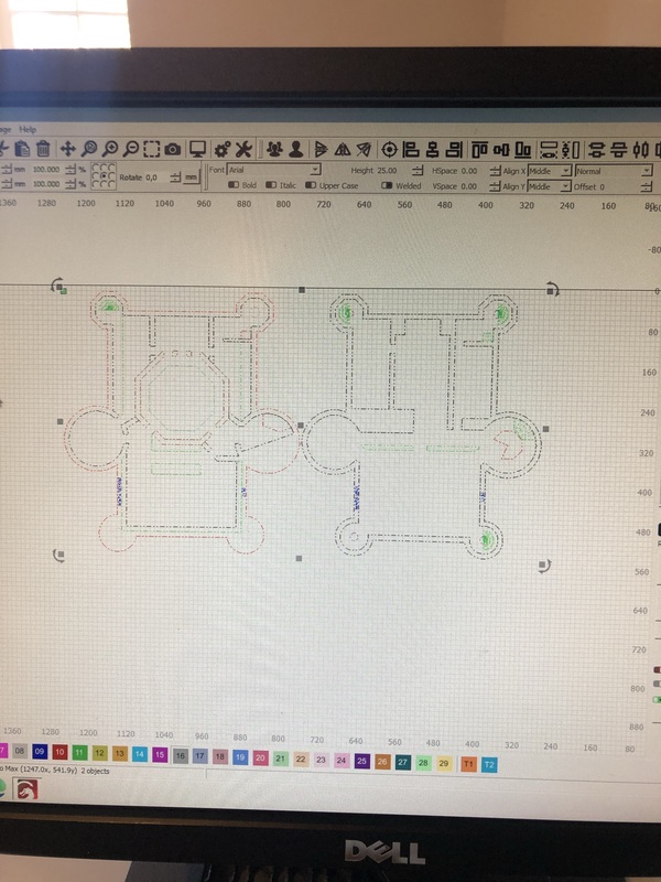
- Lasercutting the floors in acrylic
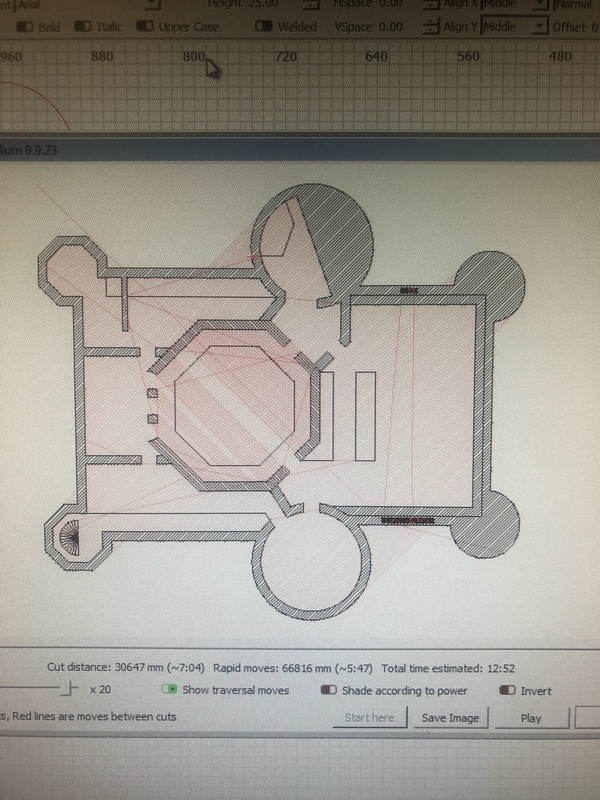
Lightburn has the option to delete duplicate lines and to automatically connect open vectors, which is an amazing feature that I think all vector based programs should have (I know Rhino has it, but I mainly use Illustrator which doesn’t have it). Lightburn also has lots of import and export options, that you can use to quickly import a file with open vectors and double/triple lines, let Lightburn do it’s magic, and then export to your preferred format. When Lightburn doesn’t know how to close some shapes, you can also use the Edit Nodes tool to figure out what the issue is. Usually it has to do with vectors overlapping in a way that Lightburn doesn’t recognize. Shapes have to be closed if you want to use fill to engrave them. Below the ground floor preview.
A tip when lasercutting narrow strips like this is to remove the top layer of protective plastic right after the engraving has finished, to save yourself some time on removing all of the individual pieces of plastic once the outline of the fill has been cut.
To create the walls, I used the engrave function (fill). I increased the distance between every line to 1/10 of an inch and changed the angle to 45 degrees. Below the first and second floor placement in Lightburn (I cut the first floor twice since I ended up making a mistake that just annoyed me too much). On the right the preview of the second floor.
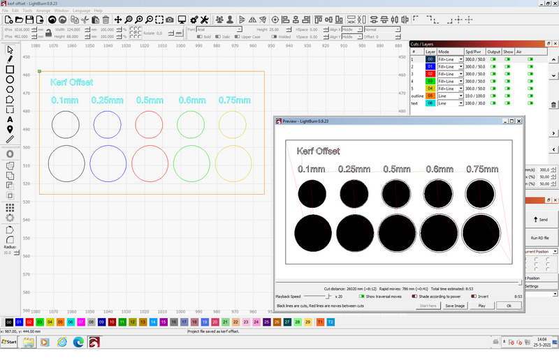
To determine the outward kerf offset for the leg slots I made a test sheet like this. However setting the kerf offset actually only moved the offset of the final line (you can see this clearly in the preview image but I didn’t check that beforehand), and not of the entire fill. Instead I made a few more engraved circles, increased the diameter a little each time and found an extra 0,75mm to work best.
- Lasercutting the ceiling and entresol legs
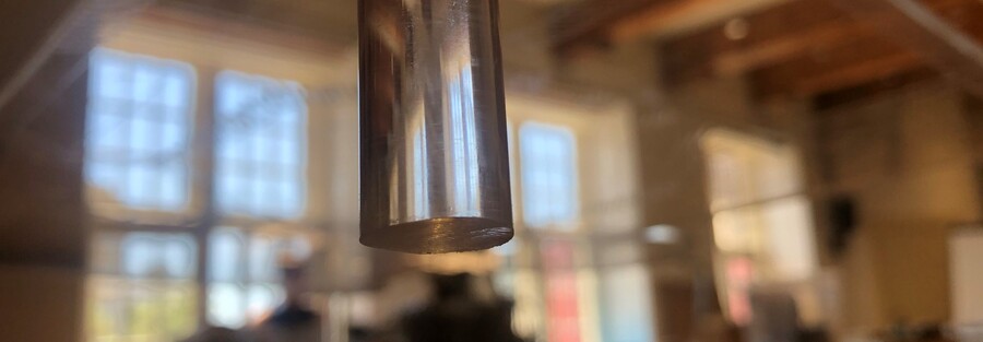
To cut the ceiling legs, I first made a ‘mold’ to hold the acrylic cilinder in place. Then I measured the exact length I needed them to be and cut that area multiple times until it went all the way through. I secured the cilinders with some tape, and wrapped some clear tape around the area to be cut to minimize the amount of smoke interfering with a clean cut. This ended up not making much of a difference, with or without tape the cuts were pretty clean. The thicker the leg, the more uneven the cut turns out. This is because you can only focus the laser in one spot. You can see lasercut lines and a bit of irregularity below. You can sand it or leave it; here I left it since it was at the bottom of the leg, which fits in the leg slot so you don’t see it.
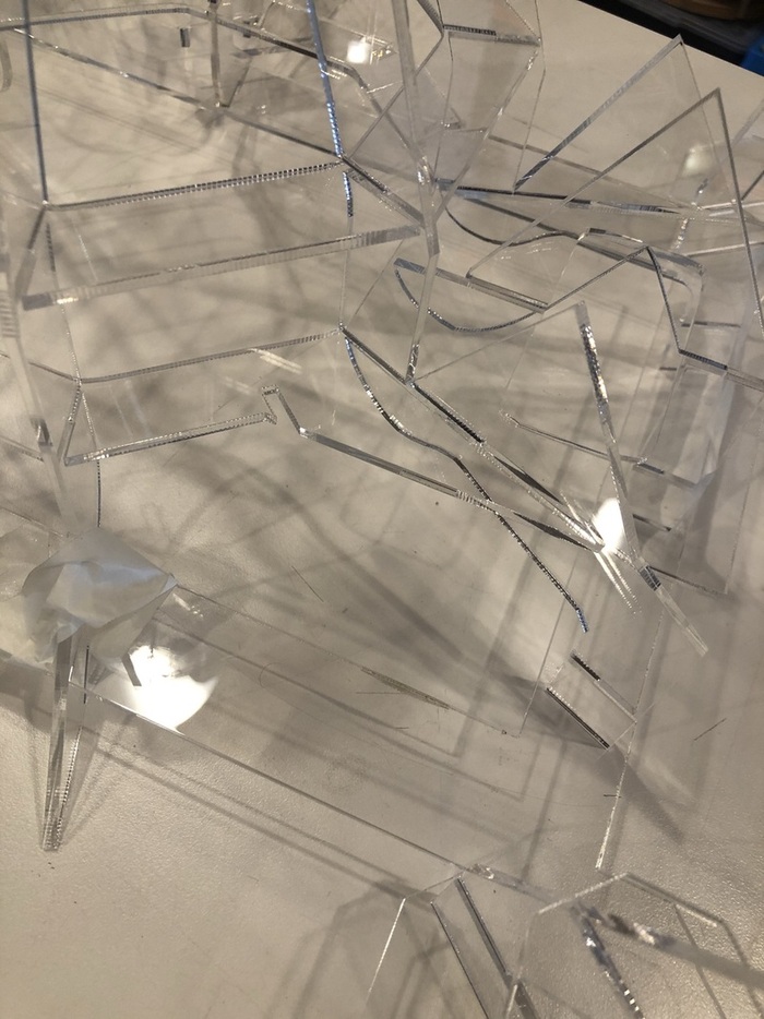
- Gluing the floors with acetone
Acetone is a very strong solvent that can be used to glue acrylic to acrylic. Steps taken:
- Clean pieces to be glued together (can be done with acetone as well)
- Place pieces how you want them to be connected
- Use a syringe to pour the liquid over the area to be bonded. You should see the acetone flowing between the two parts
- Make sure to pour enough, and don’t move the parts too much afterwards; acetone evaporates quickly
- Leave it alone for about a day
In the steps specified here it’s mentioned that it’s easiest to use the two most coarse edges if possible, since that would allow more liquid to fill the area to be bonded. We actually found that it worked way better if the surfaces were as flat as possible, so there was as much connection between the surfaces as possible. You can usually clean acetone residue with alcohol or more acetone. However, if you pour too much acetone (which happened a couple of times), it will destroy the top layer of the material around the bonded area, and you can’t really fix that.
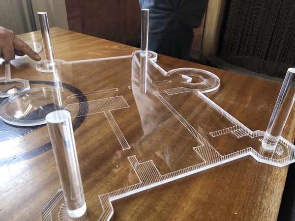
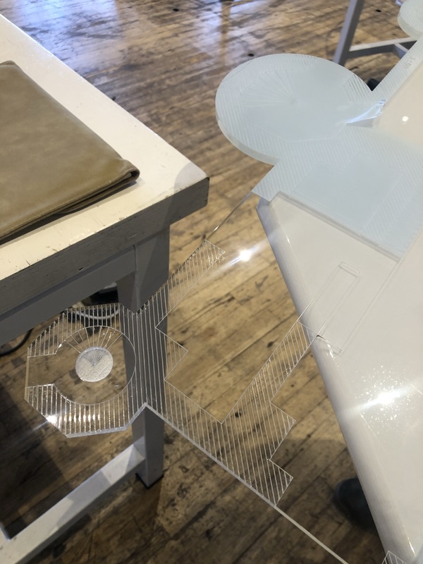
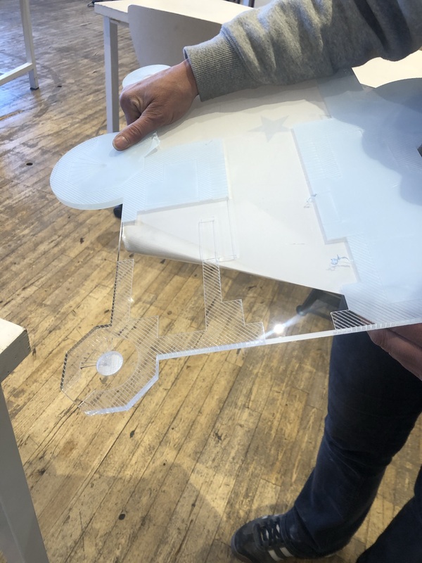
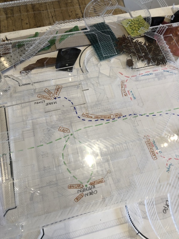
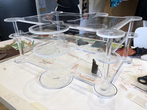
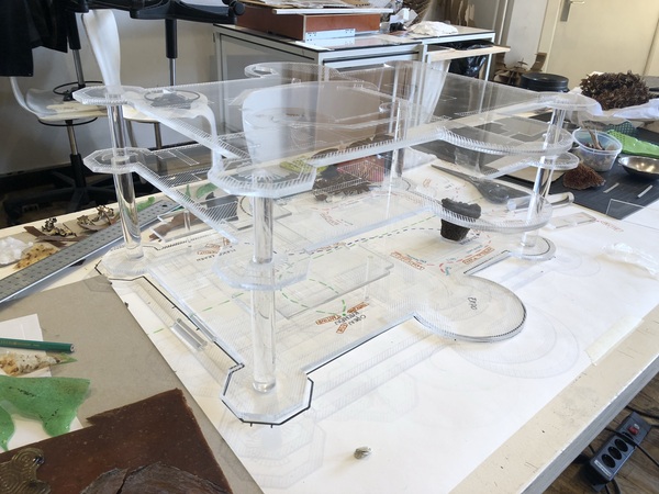
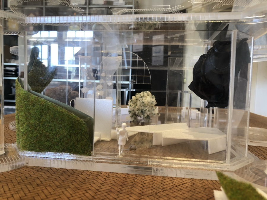
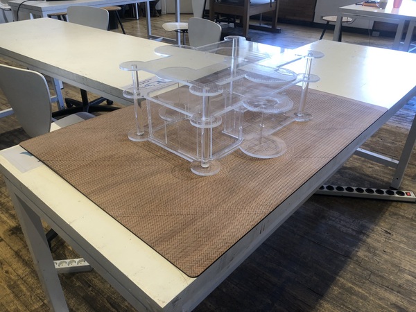
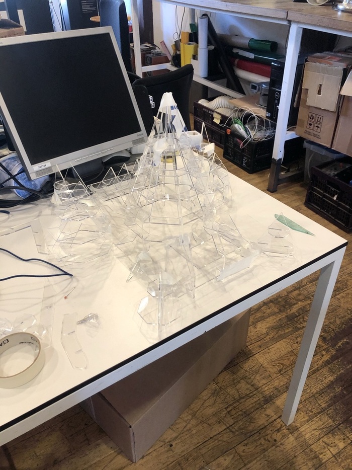
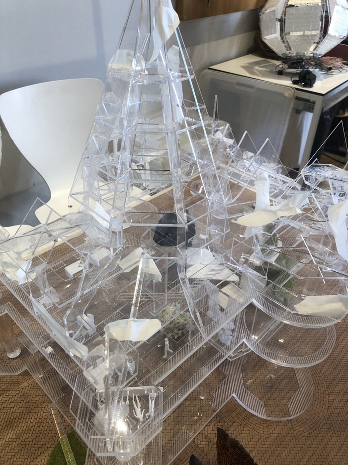
Intermediate results
The transparent base allows for drawings and notes underneath to be part of the story, visualizing the ideas for the future lab.
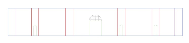
- Ground floor inner walls
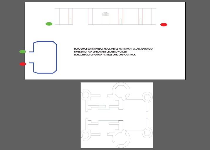
On the ground floor we wanted We tried bending the walls with pre-engraved cuts, which seemed promising at first. I determined the length and the position to bend in Illustrator using the ground floor plan. The model had to be flipped halfway through lasercutting to cut the corners that had to bend in the other direction.
However it was pretty hard to get all the different corners to align perfectly and the bent parts ended up breaking easily (also partially because the cuts were deeper than the cuts for the succesful tryouts). We tried fixing it with acetone but the connections were too fragile.
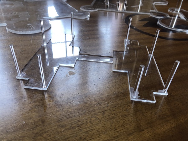
I ended up breaking all of the walls that I wanted to bend, so I could try out whether it was possible to glue them together with acetone and a narrow base. This worked out just fine so we went with this option. You can use the LBRN walls file at the bottom and cut all the way through the acrylic (higher power/lower speed) so you end up with separate walls, place them in the narrow base, tape the whole construction to add some stability and pour acetone between the walls and where the walls and base touch.
Walls already serving their purpose:
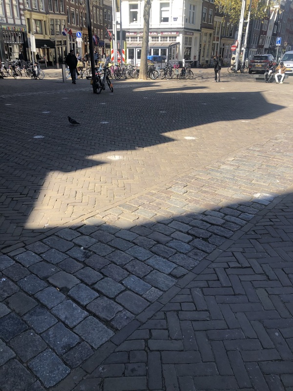
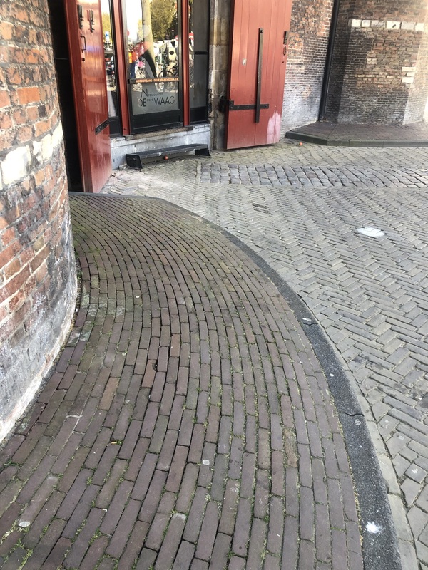
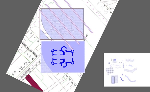
- Making the square in Illustrator
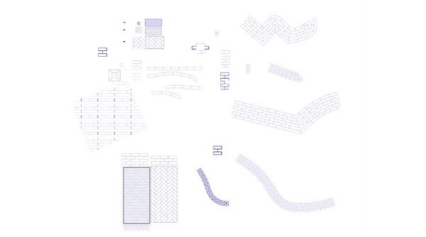
To place the Waag within it’s context on the Nieuwmarkt, we made a scaled square for the model to be placed on. First I investigated the brick pattern and the size and approximate placement of the large ‘stripes’ on the square:
I then made brushes and patterns in Illustrator of these bricks to cover the square. Of course Illustrator doesn’t actually cut out clipping masks, so I had to manually cut the shapes in Lightburn (again the one program that seems to have all of the tools I’m missing in Illustrator). I’ve added the final LBRN file for the square below.
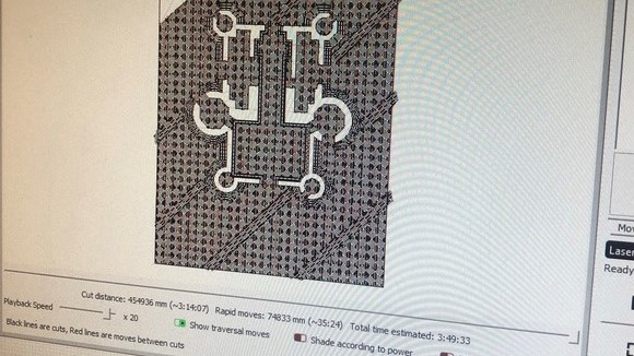
- Lasercutting the square
This took more than four hours, but it turned out pretty nice. You can see the difference in focus of the laser on one side of the square, since the laser bed isn’t perfectly level anymore. After that I used beeswax to finish the wood.
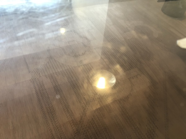
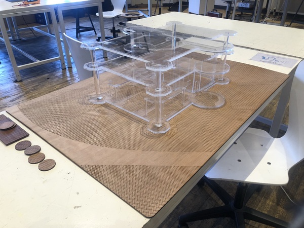
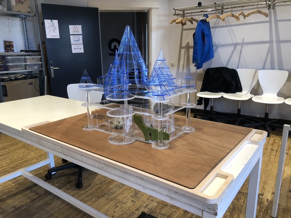
The model on the square:
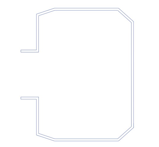
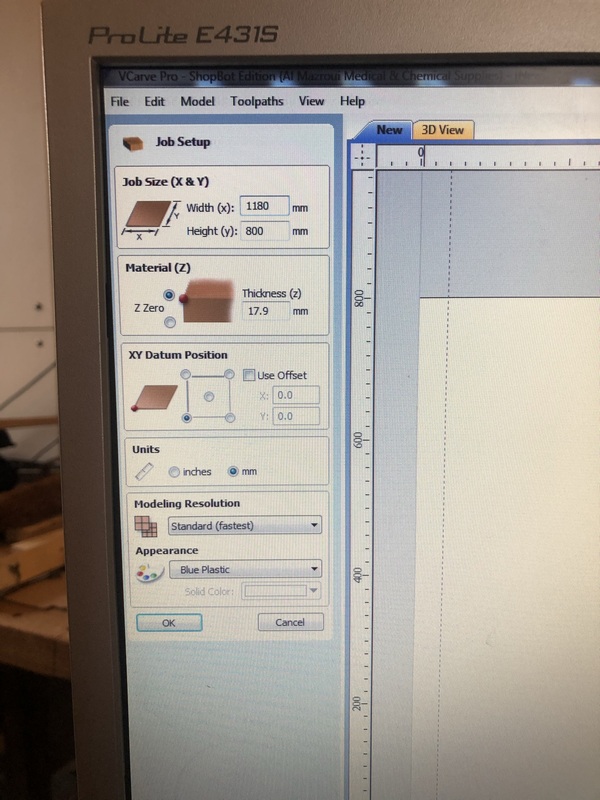
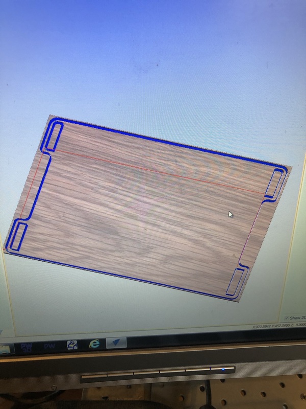
- Milling the underlayer for the square
This was pretty straightforward; I made a design in Illustrator (file below) that was slightly bigger than the square and added handles. Then I milled it on the Shopbot out of 18mm thick plywood and after that I sanded the wood.
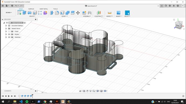
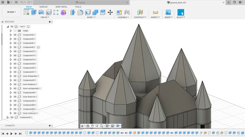
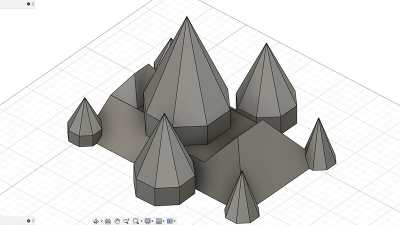
- Modeling the roof in Fusion360
To model the roof, I went back to the official plans of the Waag building to figure out angles and heights. after that I created a new file for the roof since I wanted to keep the parts of the roof separate in the original file.
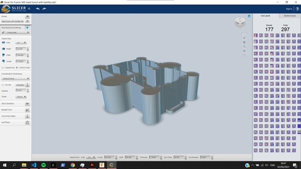
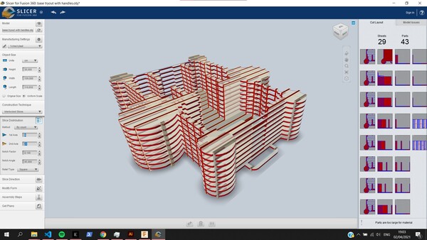
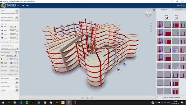
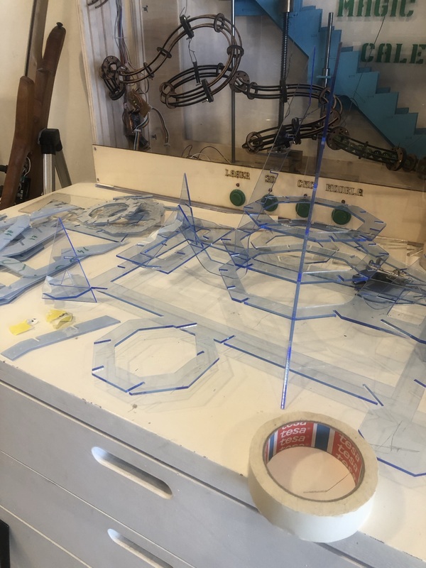
- Slicing the roof in Slicer for Fusion360
I tried two techniques: interlocked slices and radial slices.
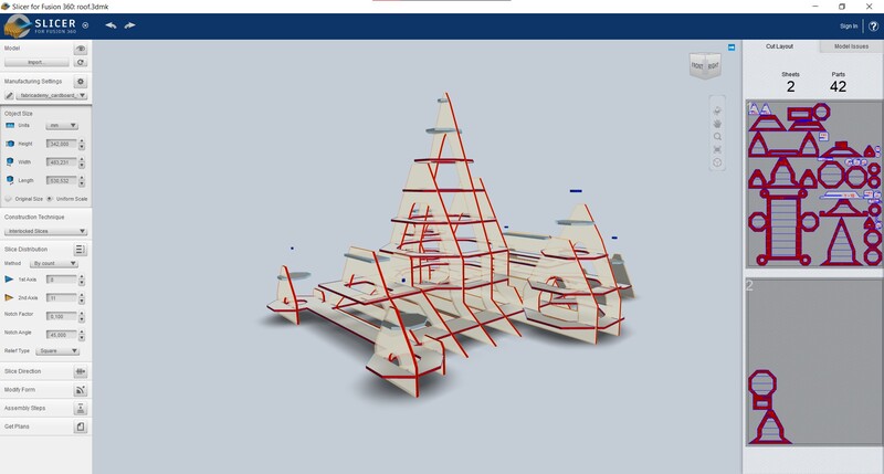
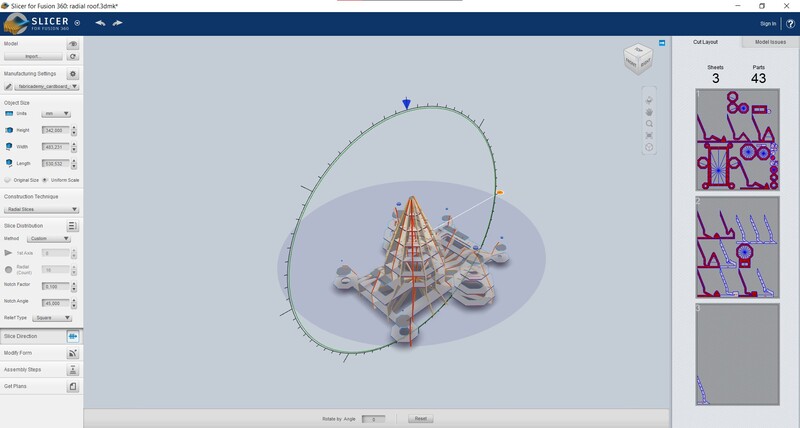
Depending on the dimensions of the material used, I changed the lay-out of the slices.
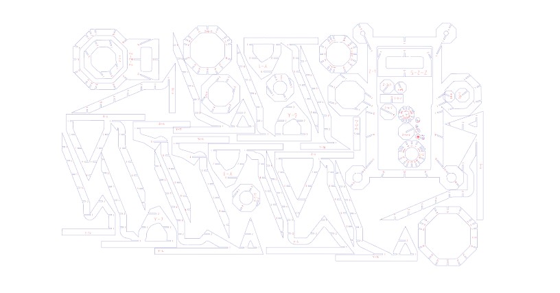
- Lasercutting the roof iterations
First testing in cardboard (3mm thick):
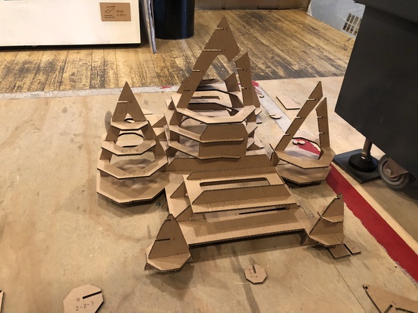
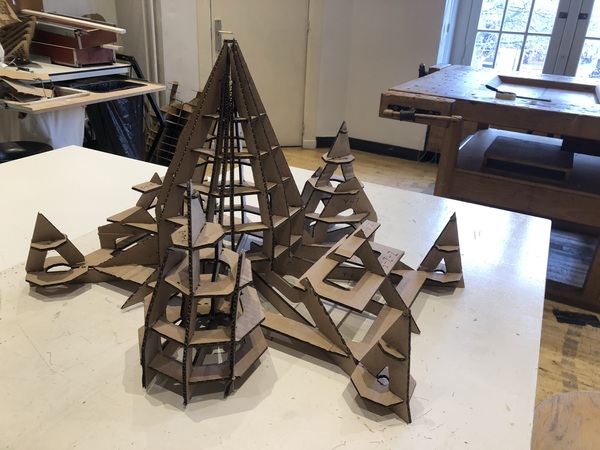
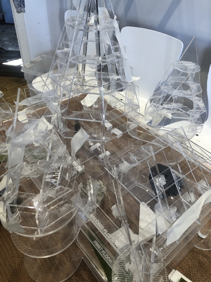
We decided to continue with the radial sliced model. In next iterations, we got rid of the bottom of the vertical slices, nearly halved the amount of vertical slices necessary and evened out the top of the theatrum.
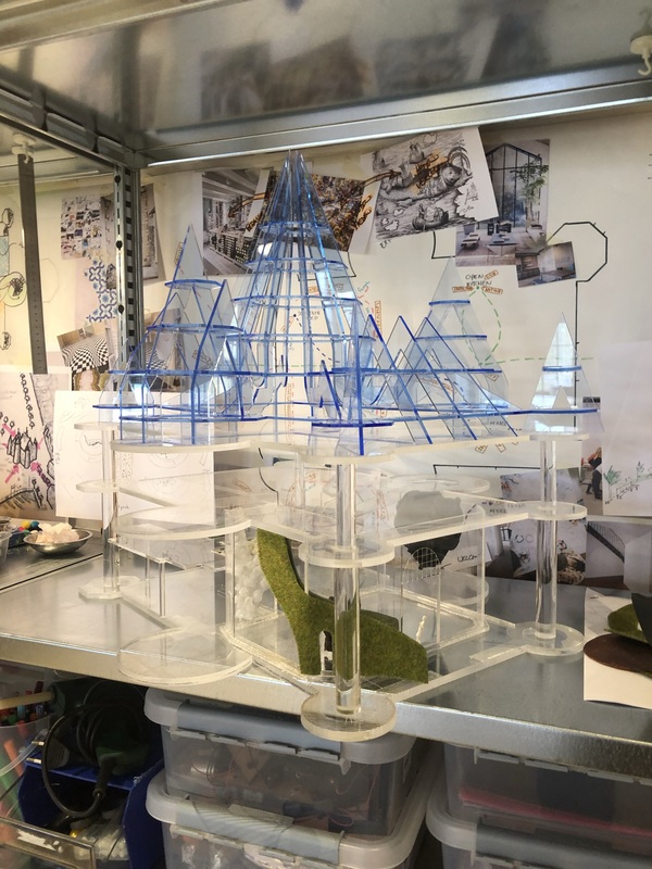
The 3mm acrylic I used ended up being very irregular, with variations in thickness between 2.9 and 4.1mm, which made proper pressfit impossible. I ended up giving all of the pieces an inward offset of 0.2mm, as an estimated average of thickness (so 3.4mm total slot thickness). For most parts this ended up working; a few pieces I had to redo multiple times but in the end it was possible to assemble the roof with just a few critical points where the acrylic cracked.
This was supposed to be the final iteration, but we didn’t like the blue hue of this specific acrylic in the end. This was the only 3mm see-through acrylic sheet that we had enough of to make the roof, so we hoped it was going to look nice. It looked good by itself but placed on top of the Waag model it just looked strange (reminded me ), so we decided to order new transparent 3mm sheets. This also gave me the opportunity to improve the model even more. I removed 6 of the vertical slices to make the model even more open and accessible.

Final model