NeoPixel Waag logo
I’m gonna make the Waag logo emit light with NeoPixels, with 3 modes that you can switch between: white light that can be dimmed with a pot meter, color that can be changed with the same pot meter, and rainbow mode (a standard NeoPixel option).

Neopixels and Arduino Mini
What I’m using:
- Arduino Pro Mini (for prototyping)
- NeoPixel 1/4 Ring (SK6812) Datasheet
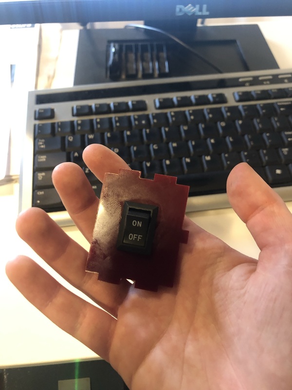
- Rotary switch This one
- Button switch
- Jumper wires
- Resistors
- Breadboard
- Acrylic lasercut Waag logo (logo can be found here)
Neopixel specifications:

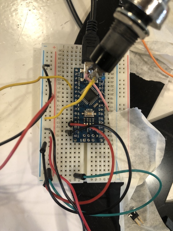
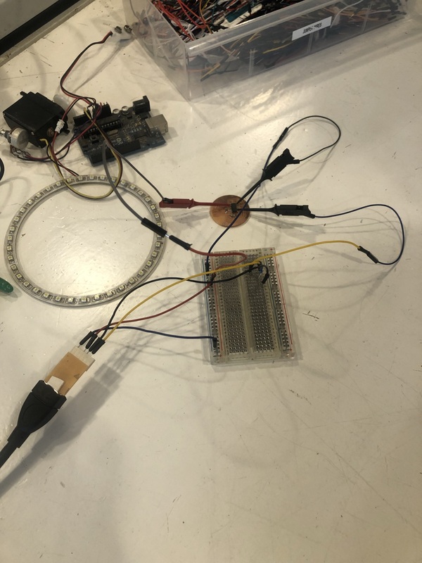
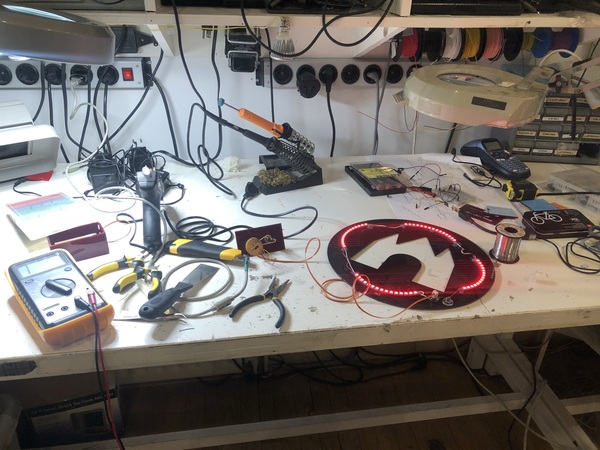
Chaotic breadboard wiring:
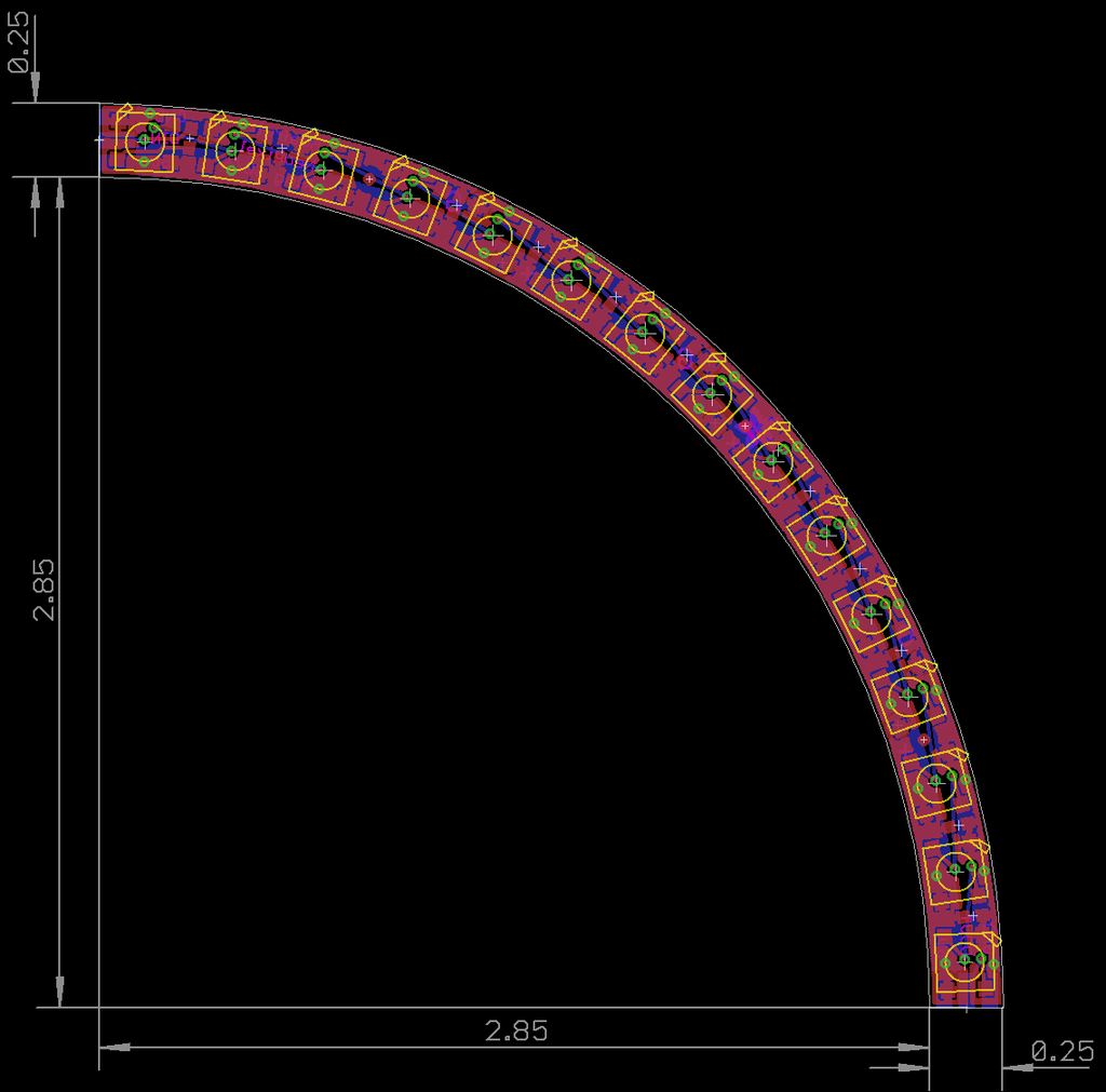
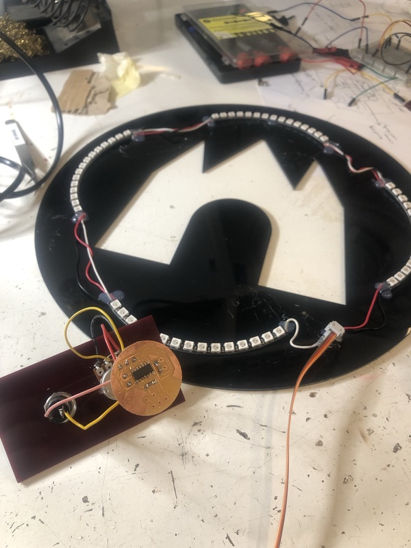
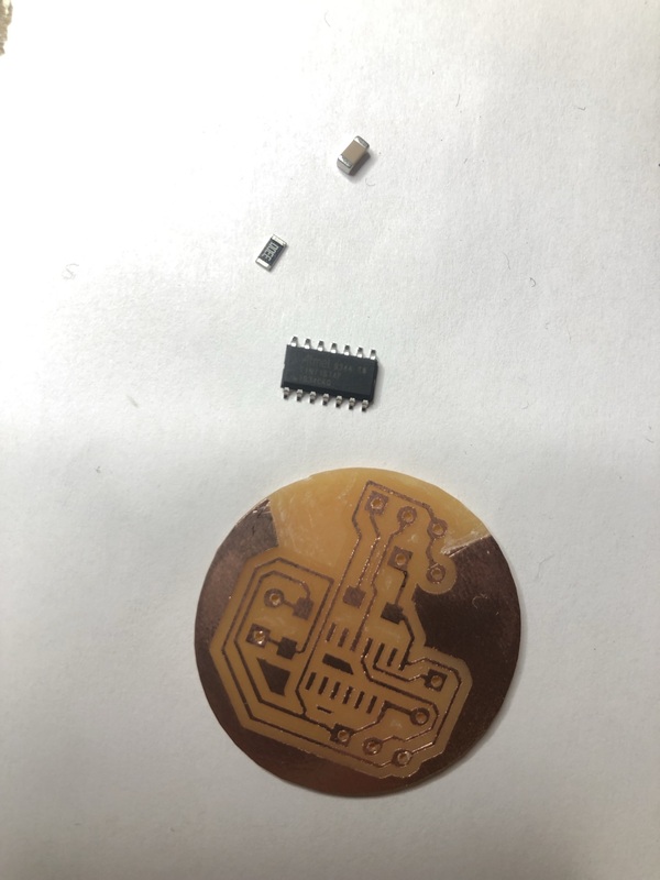
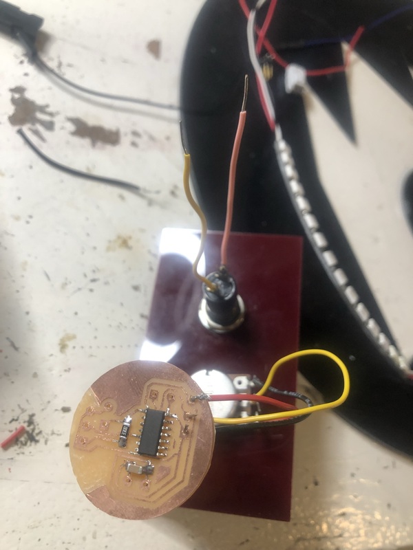
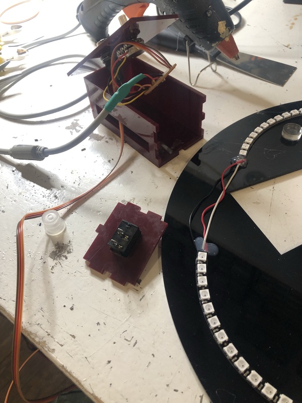
First I soldered the NeoPixel quarter rings into a circle. I used wires of about 10cm long so I could make a wider circle; since we want to mount the NeoPixels to the Waag logo it won’t be (too) noticable that the circle is interrupted. Below you can see the soldered neopixels and a sneak preview of the milled PCB.
- I first tried a 500 Ohm resistor between the DATA-IN and the Arduino, but that was too much resistance; 330 Ohm worked perfectly.
- I used a pulldown resistor for the switch (pulldown is between ground and the button); this is to prevent shorting the circuit. The resistor is there to prevent the short by limiting the current flowing; typically 1k to 10k in value..
- I used the strandtest.ino file in the NeoPixel library in the Arduino IDE to test whether it worked. First it wouldn’t upload, but that was because I specified the wrong board (Arduino Mini instead of Arduino Pro Mini). Then the ring wouldn’t turn on, first because some connections weren’t properly soldered and then because I connected to A6 instead of D6.
Arduino code
Notes on the code:
- Analog values between 0 and 1023 for the potentiometer; 65536 values in the color range so 65536 / 1023 so multiply value by about 64 to use the potentiometer to scroll through the colors.
- For the dimming of the white light: 0-1023 values divided by 4 is about 0-255.
Code used:
#include <Adafruit_NeoPixel.h>
int pushButton = 4;   // choose the input pin (for a pushbutton)
int pushButtonRotary = 2;

// Potentiometer
int potSensor = A0;
int currentColourValue;

int lastState = 0; // the previous state from the input pin
int currentState = 0;    // the current reading from the input pin
static int hits = 0;

// Which pin on the Arduino is connected to the NeoPixels?
#define LED_PIN    7

// How many NeoPixels are attached to the Arduino?
#define LED_COUNT 60

// Declare our NeoPixel strip object:
Adafruit_NeoPixel strip(LED_COUNT, LED_PIN, NEO_GRB + NEO_KHZ800);

void setup() {
  // initialize serial communication at 9600 bits per second:
  Serial.begin(9600);
  // make the pushbutton's pin an input:
  pinMode(pushButton, INPUT);
  //  pinMode(pushButton, INPUT_PULLUP);

  strip.begin();           // INITIALIZE NeoPixel strip object (REQUIRED)
  strip.show();            // Turn OFF all pixels ASAP
  strip.setBrightness(50); // Set BRIGHTNESS to about 1/5 (max = 255)
}

void loop() {
  lightSwitcher();
}

void lightSwitcher() {
  currentState = digitalRead(pushButton);
  int sensorValue = analogRead(potSensor);

  Serial.println("lightSwitcher loop start");
  Serial.print(sensorValue);  // potentiometer value 0-1023
  Serial.println(" potentiometer value");
  Serial.print(currentState); // HIGH (1) or LOW (0), button pressed or not pressed
  Serial.println(" button value");

  if (currentState != lastState) {
    if (currentState == HIGH) {
      hits = hits + 1;
      Serial.print(hits);
      Serial.println(" hits");
      delay(1);
    }
  }

  if (hits == 0) {
    whiteLight();
  }

  if (hits == 1) {
    rainbow(1);
    hits = hits + 1; // otherwise we can't exit the rainbow part
  }

  if (hits == 3) {
    potentioMeter();
  }

  if (hits == 4) {
    whiteLight();
    if (currentState != lastState) {
      if (currentState == HIGH) {
        hits = 0;
        Serial.println(hits);
        Serial.println("reset hits");
      }
    }
  }
}

void whiteLight() {
  int sensorValue = analogRead(potSensor);
  for (int i = 0; i < strip.numPixels(); i++) { // For each pixel in strip...
      strip.setPixelColor(i, 255, 255, 255, 255);
      strip.show();                          //  Update strip to match
      delay(1);                           //  Pause for a moment
      strip.setBrightness(sensorValue / 4); // 0-1023 values divided by 4 is about 0-255
    }
}

void potentioMeter() {
  Serial.println("potentioMeter loop start");
  int sensorValue = analogRead(potSensor);
  for (int i = 0; i < strip.numPixels(); i++) { // For each pixel in strip...
    strip.setPixelColor(i, strip.gamma32(strip.ColorHSV(sensorValue * 64)));
    strip.show();                          //  Update strip to match
    delay(1);                           //  Pause for a moment
  }
  currentState = digitalRead(pushButton);
  Serial.print(currentState); // HIGH (1) or LOW (0), button pressed or not pressed
  Serial.println(" button value, we're in the potentiometer part now");


}

// Rainbow cycle along whole strip. Pass delay time (in ms) between frames.
void rainbow(int wait) {
  // Hue of first pixel runs 5 complete loops through the color wheel.
  // Color wheel has a range of 65536 but it's OK if we roll over, so
  // just count from 0 to 5*65536. Adding 256 to firstPixelHue each time
  // means we'll make 5*65536/256 = 1280 passes through this outer loop:
  for (long firstPixelHue = 0; firstPixelHue < 65536; firstPixelHue += 256) {
    for (int i = 0; i < strip.numPixels(); i++) { // For each pixel in strip...
      // Offset pixel hue by an amount to make one full revolution of the
      // color wheel (range of 65536) along the length of the strip
      // (strip.numPixels() steps):
      int pixelHue = firstPixelHue + (i * 65536L / strip.numPixels());
      // strip.ColorHSV() can take 1 or 3 arguments: a hue (0 to 65535) or
      // optionally add saturation and value (brightness) (each 0 to 255).
      // Here we're using just the single-argument hue variant. The result
      // is passed through strip.gamma32() to provide 'truer' colors
      // before assigning to each pixel:
      strip.setPixelColor(i, strip.gamma32(strip.ColorHSV(pixelHue)));
    }
    strip.show(); // Update strip with new contents
    delay(wait);  // Pause for a moment
  }
}
Replacing Arduino Pro Mini with Attiny
- Following these steps to program ATTiny with Arduino IDE:
“On the preferences window, locate the “Additional Board Manager URLs” text box and enter http://drazzy.com/package_drazzy.com_index.json into the field as shown below and click the OK button”.
- Then you can download the megaTinyCore library from the board manager.
- While trying to compile I encountered this error:
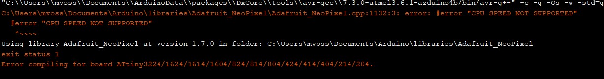 I googled CPU speed not supported, and found an easy fix here. Just change one line in the Adafruit_NeoPixel.cpp file (increasing the speed limit on the 16MHz code to 21MHz, because the clock speed of the ATTiny’s used is 20MHz) and then the code succesfully compiles for both the ATTiny 3216 & ATTiny 1614.
 - When in doubt, look at Nadieh’s documentation
- Power via pin for the switch, and use the internal pullup resistor instead of a pulldown resistor. This flipped the state of the button from high to low and low to high, so I had to change some values for the code to work again (HIGH to LOW and 0 to 1 as base states).

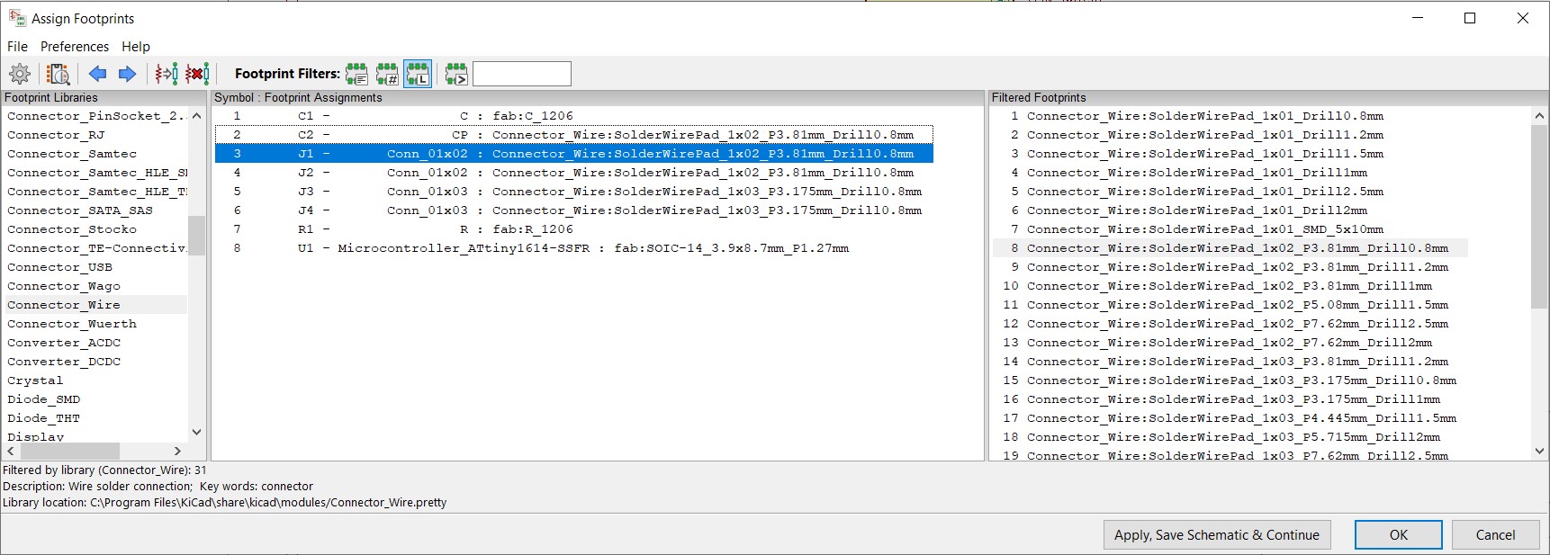
KiCad
Project schematic (including the capacitor mistake for the neopixel ring).
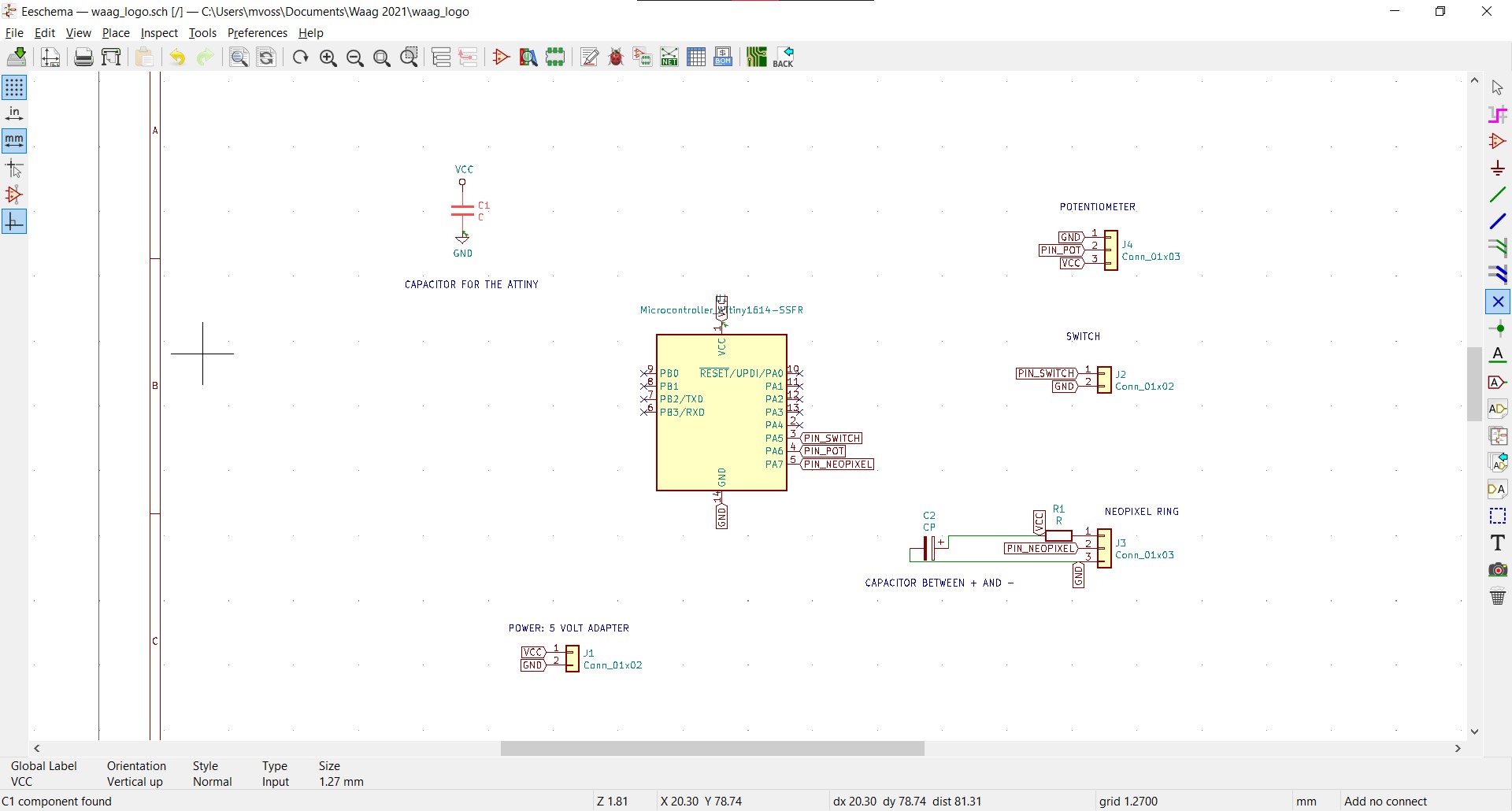
This is where I assigned all components that I was going to add with wires to through-hole solder pads.
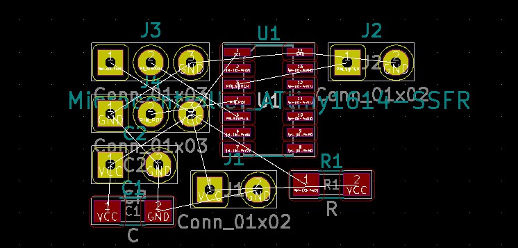
The rat’s nest:
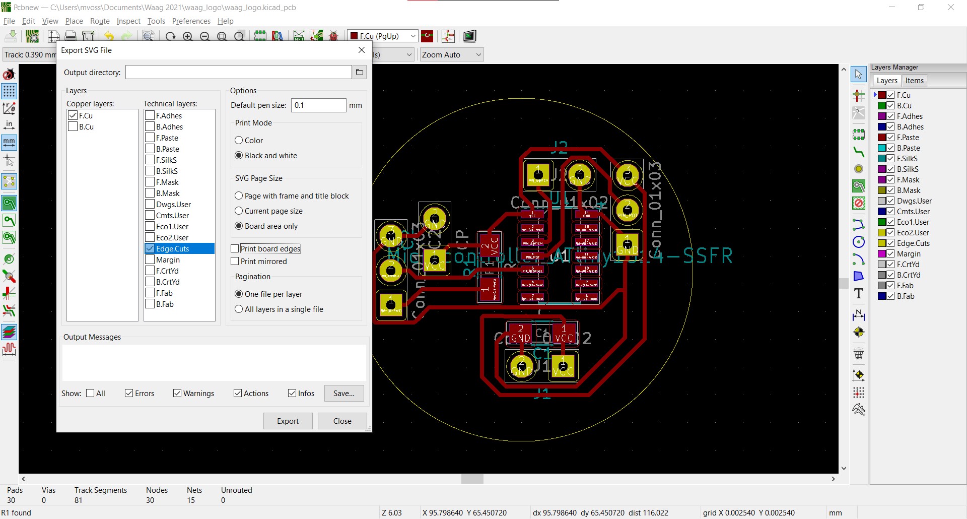
Final design with the rat’s nest all sorted out:
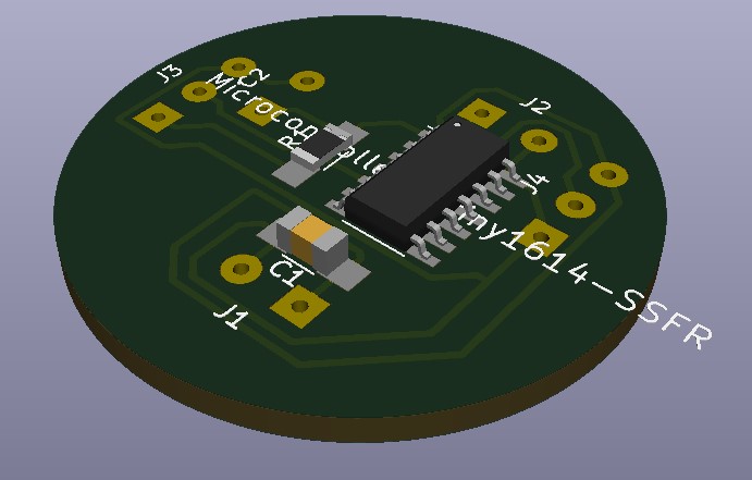
3d preview of the board:
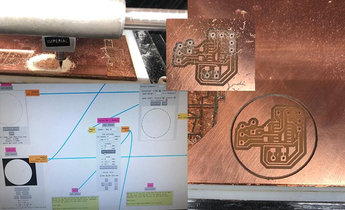
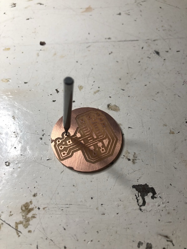
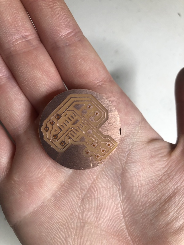
Milling the board
Below collage summary of milling the board. It wasn’t too eventful except that the through holes didn’t properly cut all the way through, so I used the milling bit afterwards to push through the holes.
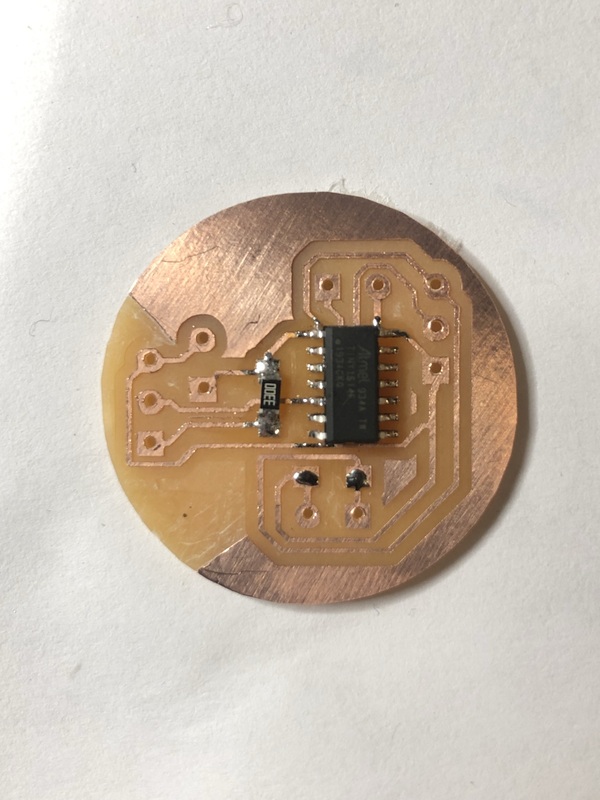
Soldering the board
Notes
- Capacitor across power supply (to protect the chip against the initial onflow of electricity): 1uF
- 330 Ohm resistor for neopixel
- Capacitor neopixel: 1000uF. Not adding a capacitor is the cause of NeoPixel flickering; I’ve added the capacitor to the board with through holes, not to the board as SMD since we didn’t have an SMD polarized capacitor of 1000uF.
I accidentally connected the 330 Ohm resistor to the power instead of the data pin in KiCad and only found out that that happened when I was already done milling, so I added a 0 ohm resistor in place of the 330 one, removed a bit of the trace between the data pin and the ATTiny and added it there.
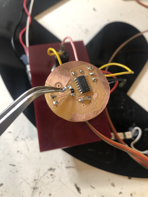
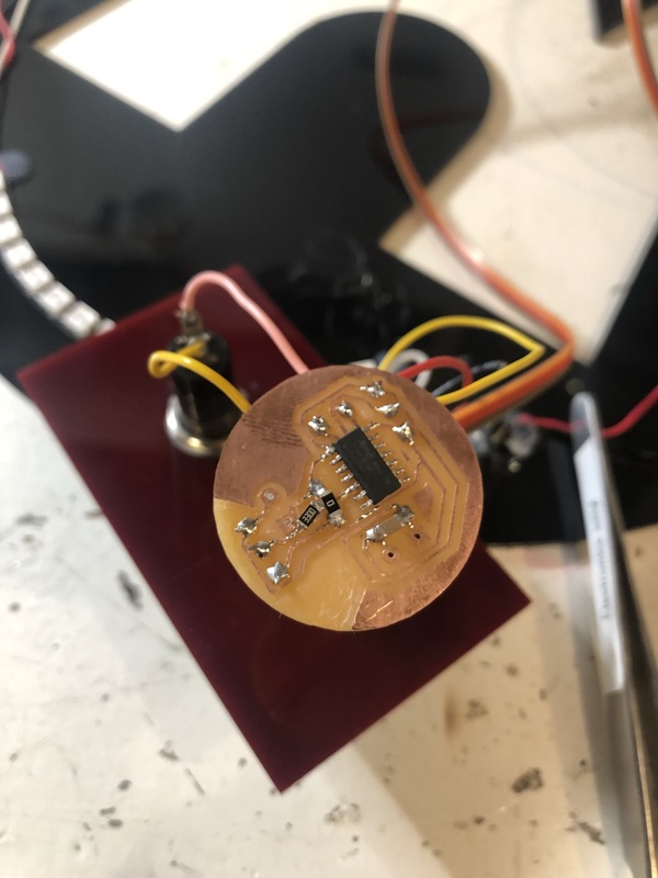
Programming the ATTiny
I used these specific hooks/claws (I forgot the name) to attach to the individual legs of the chip to program them. You can use these if you haven’t added a connector for a programmer.
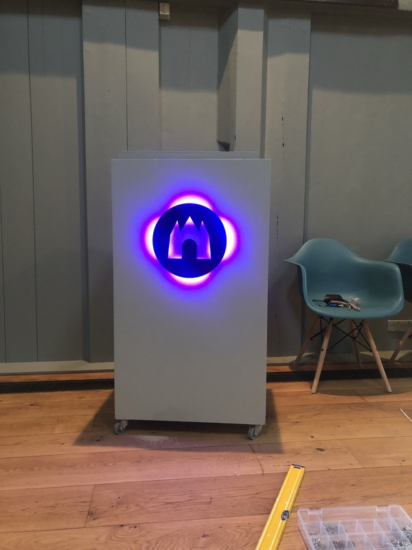
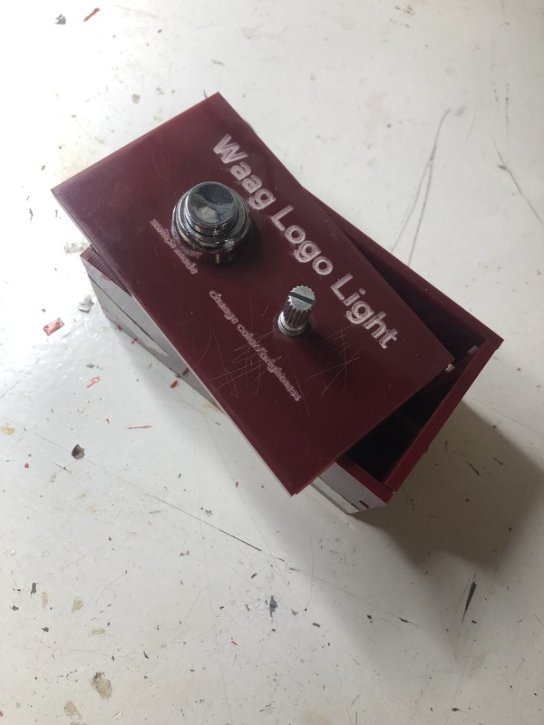
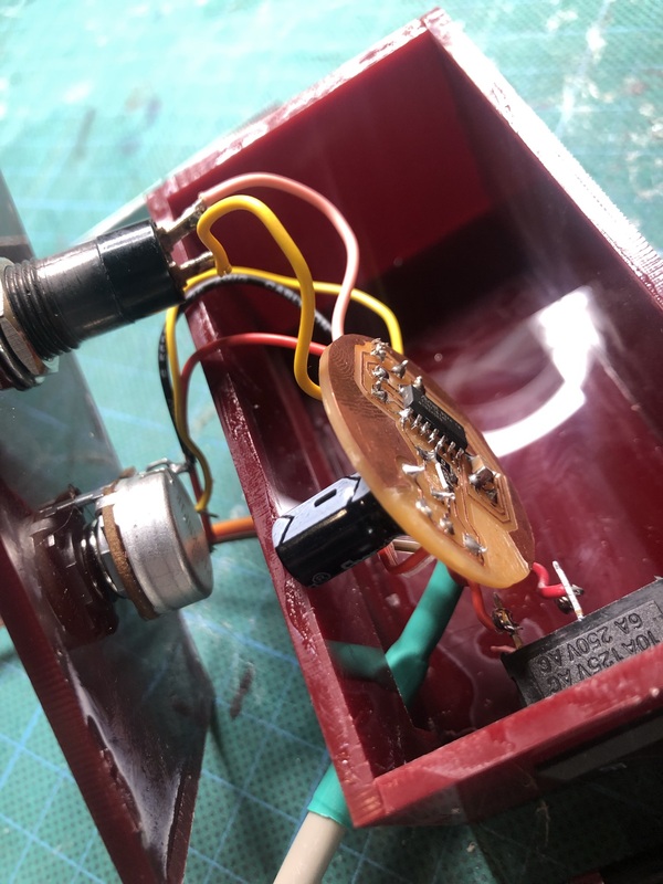
First prototype of the box:
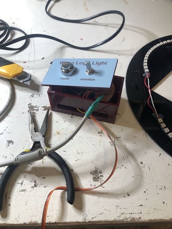
Assembly process:
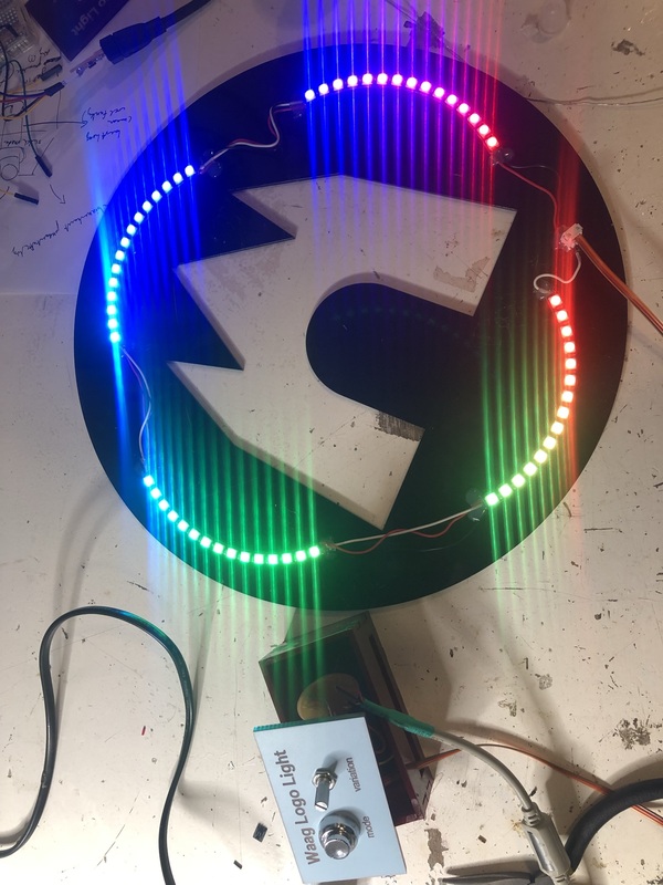
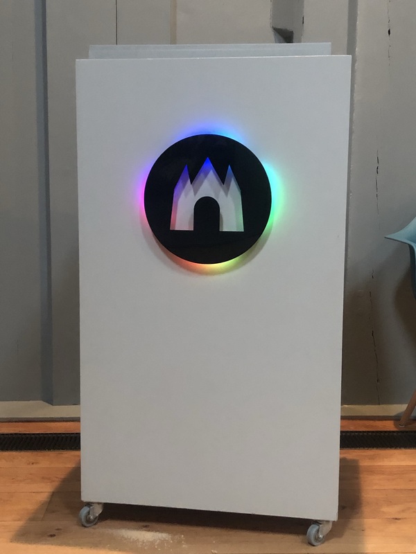
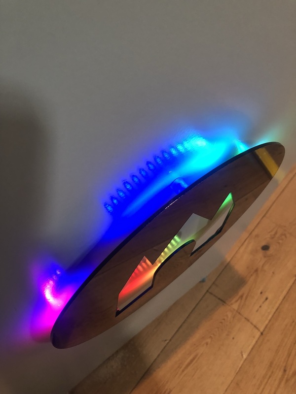
Final result: