Ultrasonic sensor motion sensing
For the Fabcharter in the lab I am using various fablab techniques to make the sentences. For the question ‘Who can use a fab lab?’ I want LEDs in the letters to light up when you walk past.
Components
- Arduino Pro Mini (for prototyping)
- Breadboard & jumper cables (also for prototyping)
- Ultrasonic sensor HC-SR04
- Neopixels
- 300 to 500 Ohm resistor
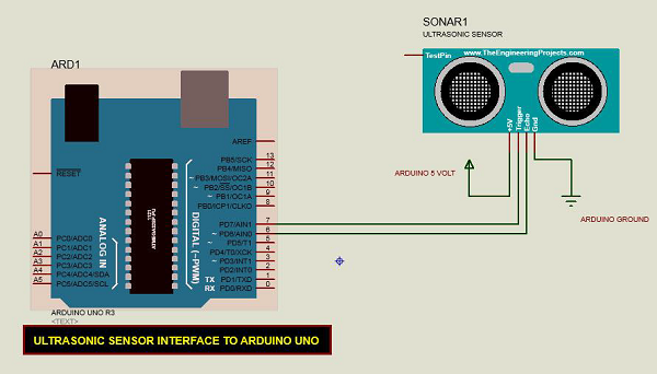
“Ultrasonic Sensor HC-SR04 is a sensor that can measure distance. It emits an ultrasound at 40 000 Hz (40kHz) which travels through the air and if there is an object or obstacle on its path It will bounce back to the module. Considering the travel time and the speed of the sound you can calculate the distance.
The configuration pin of HC-SR04 is VCC (1), TRIG (2), ECHO (3), and GND (4). The supply voltage of VCC is +5V and you can attach TRIG and ECHO pin to any Digital I/O in your Arduino Board.” (source)
Testing with Arduino and NeoPixels
I’m following this tutorial to get started with the sensor, with the schematic below as a reference; since I’m using an Arduino Pro Mini the pin-out is different for me.
The following code is what I wrote, combining the example code from the tutorial above with a NeoPixel color wipe every time there’s movement within 50 cm of the sensor.
const int pingPin = 7; // Trigger Pin of Ultrasonic Sensor
const int echoPin = 6; // Echo Pin of Ultrasonic Sensor
int lights_duration = 5000;
unsigned long previousMillis = 0;
unsigned long currentMillis = millis();


#include <Adafruit_NeoPixel.h>
#ifdef __AVR__
#include <avr/power.h> // Required for 16 MHz Adafruit Trinket
#endif

// Which pin on the Arduino is connected to the NeoPixels?
// On a Trinket or Gemma we suggest changing this to 1:
#define LED_PIN    5

// How many NeoPixels are attached to the Arduino?
#define LED_COUNT 58

// Declare our NeoPixel strip object:
Adafruit_NeoPixel strip(LED_COUNT, LED_PIN, NEO_GRB + NEO_KHZ800);

void setup() {
  Serial.begin(9600); // Starting Serial Terminal
#if defined(__AVR_ATtiny85__) && (F_CPU == 16000000)
  clock_prescale_set(clock_div_1);
#endif
  // END of Trinket-specific code.

  strip.begin();           // INITIALIZE NeoPixel strip object (REQUIRED)
  strip.show();            // Turn OFF all pixels ASAP
  strip.setBrightness(50); // Set BRIGHTNESS to about 1/5 (max = 255)
}

void loop() {
  long duration, cm;
  pinMode(pingPin, OUTPUT);
  digitalWrite(pingPin, LOW);
  delayMicroseconds(2);
  digitalWrite(pingPin, HIGH);
  delayMicroseconds(10);
  digitalWrite(pingPin, LOW);
  pinMode(echoPin, INPUT);
  duration = pulseIn(echoPin, HIGH);
  cm = microsecondsToCentimeters(duration);
  Serial.print(cm);
  Serial.print("cm");
  Serial.println();
  delay(100);
  if (cm < 50) {
    Serial.println("Neopixels will turn on");
    colorWipe(strip.Color(255, 0, 0), 50);
    colorWipe(strip.Color(0, 0, 0), 50);
  }
}

long microsecondsToCentimeters(long microseconds) {
  return microseconds / 29 / 2;
}

void colorWipe(uint32_t color, int wait) {
  for (int i = 0; i < strip.numPixels(); i++) { // For each pixel in strip...
    strip.setPixelColor(i, color);         //  Set pixel's color (in RAM)
    strip.show();                          //  Update strip to match
    delay(wait);                           //  Pause for a moment
  }
}
Lighting up individual words
I want the individual words in the phrase I’m using to light up sequentially. For this I’m using arrays:
const int pingPin = 7; // Trigger Pin of Ultrasonic Sensor
const int echoPin = 6; // Echo Pin of Ultrasonic Sensor
int lights_duration = 5000;
unsigned long previousMillis = 0;
unsigned long currentMillis = millis();


#include <Adafruit_NeoPixel.h>
#ifdef __AVR__
#include <avr/power.h> // Required for 16 MHz Adafruit Trinket
#endif

// Which pin on the Arduino is connected to the NeoPixels?
// On a Trinket or Gemma we suggest changing this to 1:
#define LED_PIN    5

// How many NeoPixels are attached to the Arduino?
#define LED_COUNT 58

// Declare our NeoPixel strip object:
Adafruit_NeoPixel strip(LED_COUNT, LED_PIN, NEO_GRB + NEO_KHZ800);

uint8_t can[] = {15, 16, 17, 18, 19, 20, 21, 22, 23, 24, 25, 26, 27};
int canCount = 13;

uint8_t use[] = {8, 9, 10, 11, 12, 13, 14, 28, 29, 30, 31, 32, 33};
int useCount = 13;

uint8_t a[] = {6, 7, 34, 35, 36};
int aCount = 5;

uint8_t fab[] = {0, 1, 2, 3, 4, 5, 37, 38, 39, 40, 41, 42};
int fabCount = 12;

uint8_t lab[] = {43, 44, 45, 46, 47, 48, 49, 50, 51, 52, 53};
int labCount = 11;

uint8_t questionmark[] = {54, 55, 56, 57};
int questionmarkCount = 4;

void setup() {
  Serial.begin(9600); // Starting Serial Terminal
#if defined(__AVR_ATtiny85__) && (F_CPU == 16000000)
  clock_prescale_set(clock_div_1);
#endif
  // END of Trinket-specific code.

  strip.begin();           // INITIALIZE NeoPixel strip object (REQUIRED)
  strip.show();            // Turn OFF all pixels ASAP
  strip.setBrightness(50); // Set BRIGHTNESS to about 1/5 (max = 255)
}

void loop() {
  long duration, cm;
  pinMode(pingPin, OUTPUT);
  digitalWrite(pingPin, LOW);
  delayMicroseconds(2);
  digitalWrite(pingPin, HIGH);
  delayMicroseconds(10);
  digitalWrite(pingPin, LOW);
  pinMode(echoPin, INPUT);
  duration = pulseIn(echoPin, HIGH);
  cm = microsecondsToCentimeters(duration);
  Serial.print(cm);
  Serial.print("cm");
  Serial.println();
  delay(100);
  if (cm < 50 && cm > 10) {
    Serial.println("Neopixels will turn on");
    colorWipe(strip.Color(255, 0, 0), 50);
    colorWipe(strip.Color(0, 0, 0), 50);
  }

  if (cm < 10) {
    for (int i = 0; i < canCount; i++) {
      strip.setPixelColor(can[i], 0, 255, 0);
      strip.show();
      delay(50);
    }
    for (int i = 0; i < useCount; i++) {
      strip.setPixelColor(use[i], 0, 255, 255);
      strip.show();
      delay(50);
    }
    for (int i = 0; i < aCount; i++) {
      strip.setPixelColor(a[i], 255, 255, 0);
      strip.show();
      delay(50);
    }
    for (int i = 0; i < fabCount; i++) {
      strip.setPixelColor(fab[i], 0, 0, 255);
      strip.show();
      delay(50);
    }
    for (int i = 0; i < labCount; i++) {
      strip.setPixelColor(lab[i], 255, 0, 255);
      strip.show();
      delay(50);
    }
    for (int i = 0; i < questionmarkCount; i++) {
      strip.setPixelColor(questionmark[i], 255, 0, 0);
      strip.show();
      delay(50);
    }
    colorWipe(strip.Color(0, 0, 0), 50);
    Serial.println("done");
  }
}

long microsecondsToCentimeters(long microseconds) {
  return microseconds / 29 / 2;
}

void colorWipe(uint32_t color, int wait) {
  for (int i = 0; i < strip.numPixels(); i++) { // For each pixel in strip...
    strip.setPixelColor(i, color);         //  Set pixel's color (in RAM)
    strip.show();                          //  Update strip to match
    delay(wait);                           //  Pause for a moment
  }
}
After this I wanted to use nicer colors to create more of a gradient. First I just changed the RGB values accordingly but the lights turned out way too bright, so I figured I should try HSV colors instead (also to change the hue of the gradient faster). After some trial and error with the color values my if loop ended up like this:
if (cm < 50) {
    Serial.println("Neopixels will turn on");

    int gradientHue = cm * 1310;            // Color wheel has a range of 65536, mapped over a distance from 0-50 cm here so 0-50cm is 0-65536 > 65536/50=approx 1310
    for (int i = 0; i < canCount; i++) {
      strip.setPixelColor(can[i], strip.gamma32(strip.ColorHSV(gradientHue)));
      strip.show();
      delay(50);
    }
    for (int i = 0; i < useCount; i++) {
      strip.setPixelColor(use[i], strip.gamma32(strip.ColorHSV(gradientHue + 4000)));
      strip.show();
      delay(50);
    }
    for (int i = 0; i < aCount; i++) {
      strip.setPixelColor(a[i], strip.gamma32(strip.ColorHSV(gradientHue + 8000)));
      strip.show();
      delay(50);
    }
    for (int i = 0; i < fabCount; i++) {
      strip.setPixelColor(fab[i], strip.gamma32(strip.ColorHSV(gradientHue + 12000)));
      strip.show();
      delay(50);
    }
    for (int i = 0; i < labCount; i++) {
      strip.setPixelColor(lab[i], strip.gamma32(strip.ColorHSV(gradientHue + 16000)));
      strip.show();
      delay(50);
    }
    for (int i = 0; i < questionmarkCount; i++) {
      strip.setPixelColor(questionmark[i], strip.gamma32(strip.ColorHSV(gradientHue + 20000)));
      strip.show();
      delay(50);
    }
    colorWipe(strip.Color(0, 0, 0), 50);
    Serial.println("done");
  }
FabTinyISP
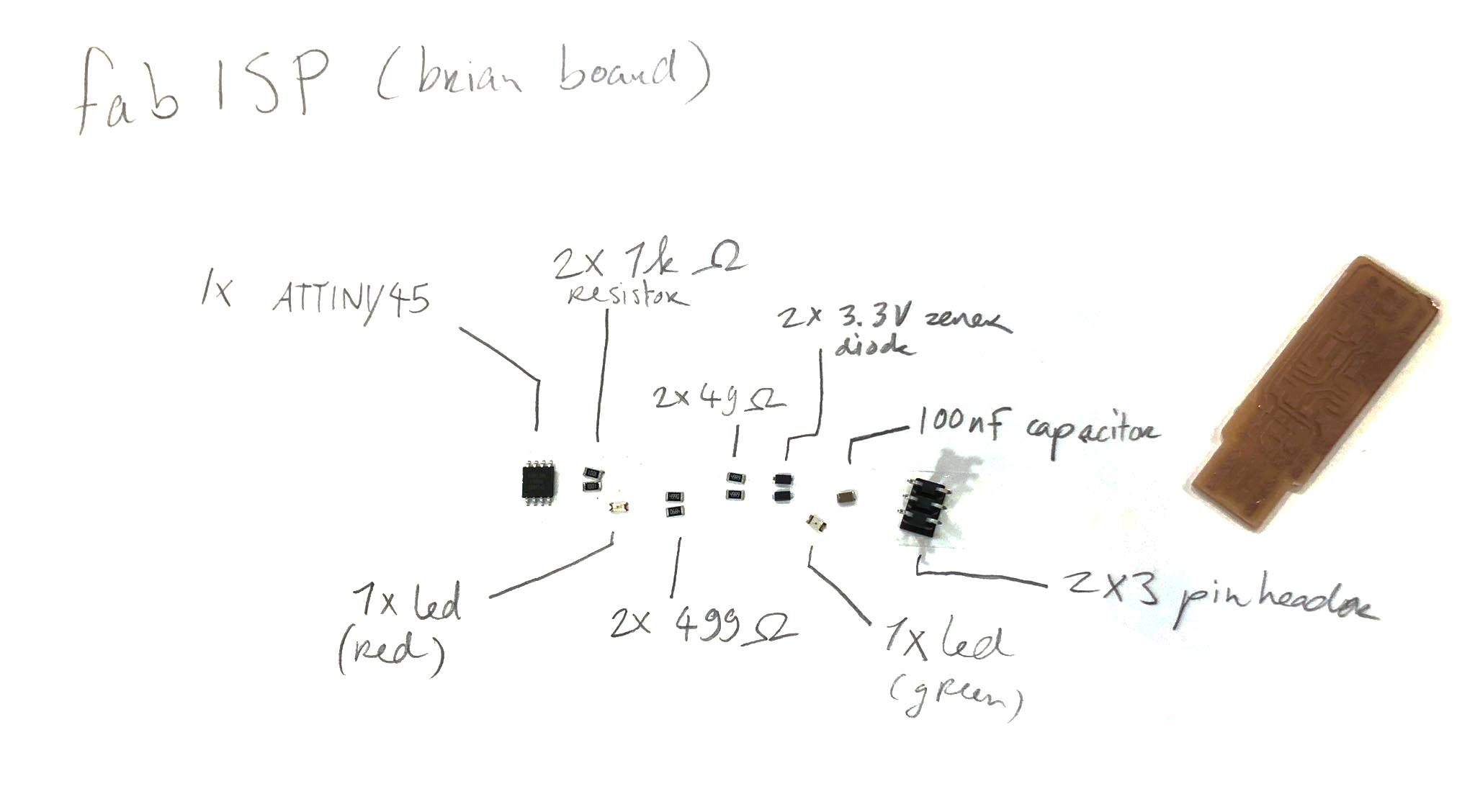
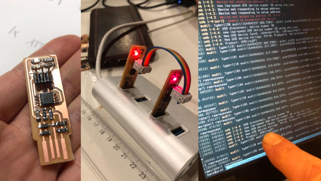
 Before I started my own board I made a FabTinyISP. Since I’m using an ATTiny85 I have to make it to program this older chip. This board is documented here. Also check out Henk’s documentation.
All components of the board together:
Programming the soldered ISP with Henk’s ISP:
KiCad designing
Initially I planned on using an ATTiny412 for my board but since my sketch is over 4kb that won’t work. I’m going to be using an ATTiny85 instead since it has 8kb of memory. I need 3 pins: 2 for the motion sensor and 1 for the neopixel strip.
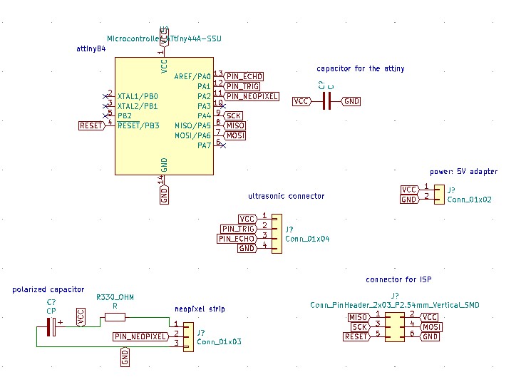
Components on the board:
- ATTiny85 (datasheet)
- HC-SR04
- Neopixel strip
- 330 Ohm resistor for neopixels
- capacitor neopixels: 1000 uF (uF is the same as µF, microfarad)
- capacitor across power supply (to protect the chip against the initial onflow of electricity): 1uF
- FTDI pins (for programming the board)
Steps
- Open a new project in KiCad (Ctrl+N)
- Open schematic layout editor
- Place components (use Place > symbol or shift+A). Here I encountered the following error:
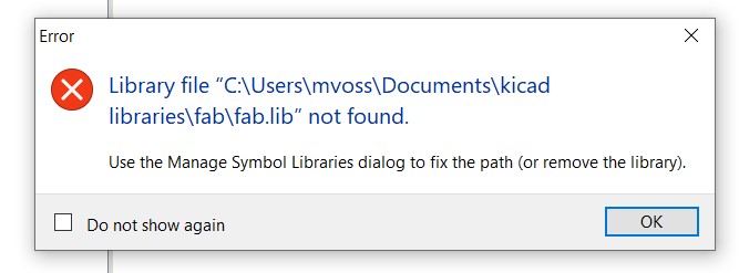 I think I accidentally deleted my kicad libraries when I was cleaning up my computer, so I’m reinstalling the fabacademy library first following the steps here. Following the steps didn’t work properly so instead of adding fab.kicad_sym to the symbol library in step 4 I added fab.lib which worked how it was supposed to.
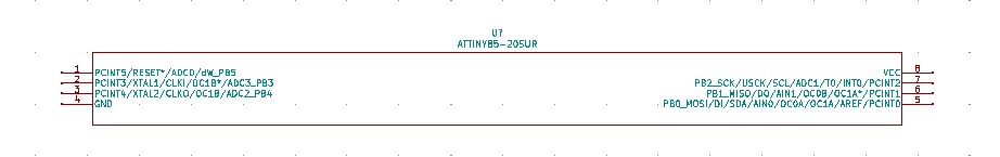
Next problem: I don’t have the footprint for the ATTiny85 so I first had to find it; the one I’m using is the 20SU. I downloaded it from ultralibrarian. The footprint in the schematic looked pretty stretched but it should be OK if the actual footprint is correct.
After this struggle Henk told me the footprint for the ATTiny45 is the same as the ATTiny85 so I could just use the one from the fab library.
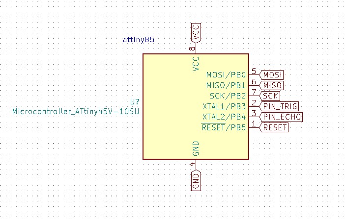
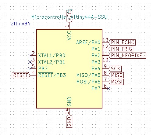
While making the project schematic I realized I was one pin short on the ATTiny85 because I didn’t take the pins necessary for programming the board into account. So I changed from a ATTiny85 to ATTiny84A because I can also program this with my newly made ISP. In KiCad I’m using the footprint of the ATTiny44 because it’s the same as for the chip I’m using now. Below on the left the ATTiny85 (with the footprint of the 45) and on the right the ATTiny84 (with the footprint of the 44).
KiCad: Schematic Editor
Pinout of the ATtiny84:
Components in EEschema:
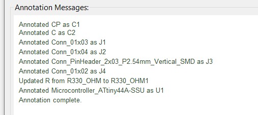
Annotate schematic:
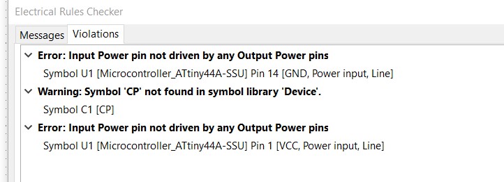
Perform electrical rules check:
 We can ignore these errors since I’m going to be powering the board with a 5V power supply.
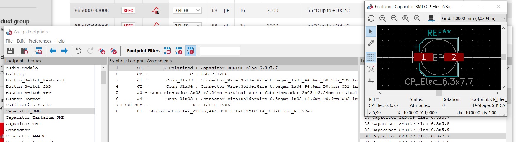
Assign footprints encountering the following error:
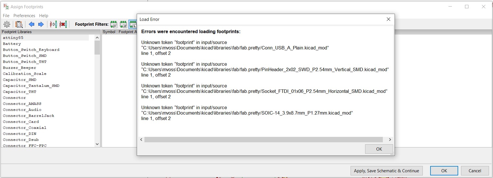 Since I wasn’t quite sure what to do I went back to the documentation for the kicad fab library to check if I did anything wrong, and I saw that I missed that I had to make sure that I had KiCad 6 installed; I’m still running KiCad 5 so i’m first updating KiCad.
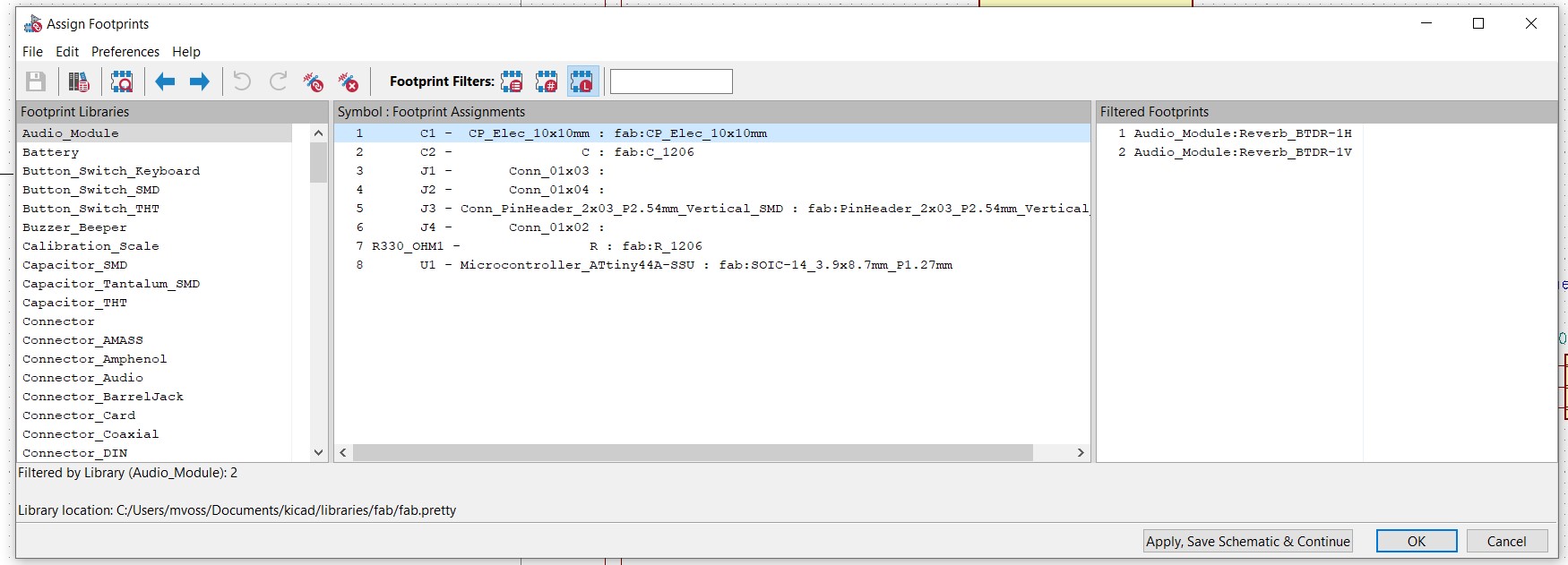
In the new version I’m walking through the steps above again where I get this electrical rules warning; I’ve replaced it now with the polarized capacitor from the fab library but I wasn’t not sure if it’s the correct one. I checked the 3d view of the pad and then I vaguely remembered that last time I connected the capacitor directly between the wires or with a through hole capacitor instead of on the board because we don’t have the polarized SMD capacitors that I need.
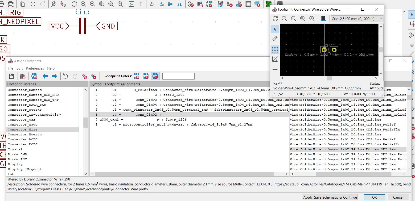
This time no errors with assigning the footprints, just some footprints that I have to assign manually:
The last time I added wire connectors all names were different so I picked the ones I thought would still work fine (I was looking for connectors with 0.8mm diameter holes but I could only find 0.9mm so that should also work I guess).
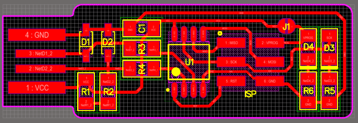
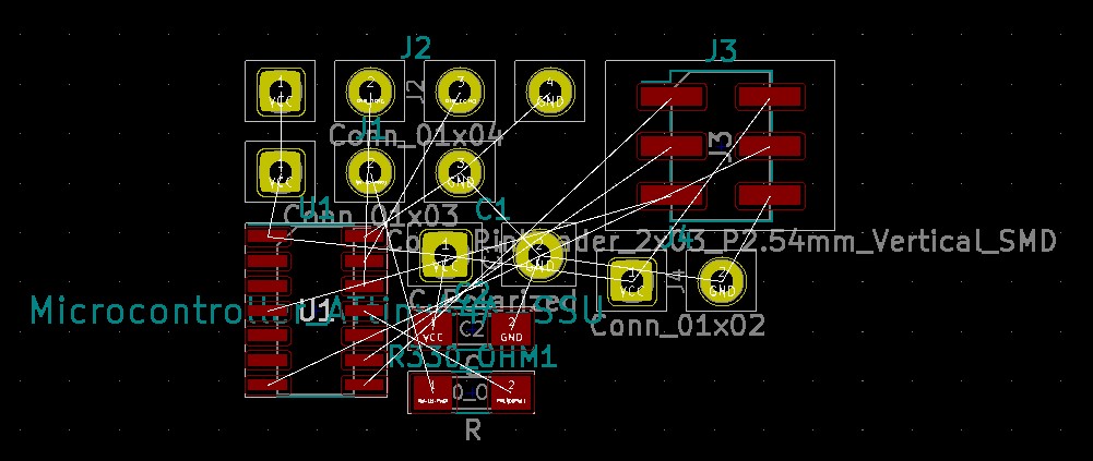
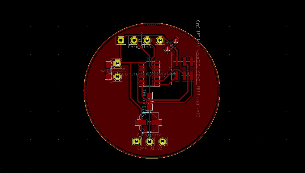
KiCad: PCB Editor
To quote Nadieh so I won’t forget: “Make sure that the VCC and GND of the microcontroller is connected to the point of power through the capacitor. In this case that meant placing the capacitor in between the lines going from the FTDI to the ATTiny.”
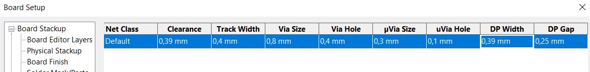
Net Classes (board setup)
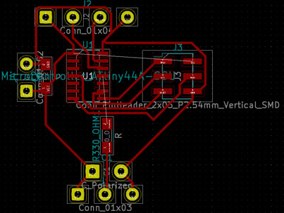
Tries:
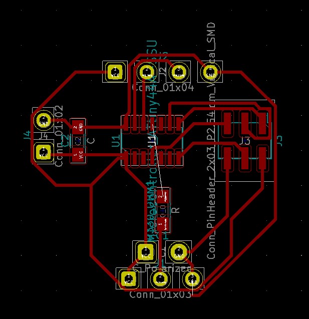
After this Henk told me I could use an electrolytic capacitor of 100uF for the neopixel (that we have in stock), so I replaced the footprint of the capacitor with that one and started over again. I couldn’t find the footprint in the fab library so I picked this one:
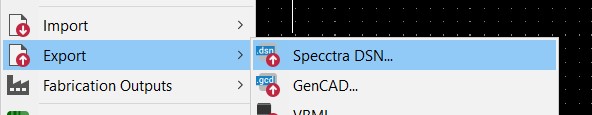
At this point I’ve started over many times already with manual routing, so I want to try autorouting to save me time. I’m following these steps. Download Layout Editor here, then localize the freerouting.jar file in the installed folder and start it (download Java Runtime Environment first). Make sure you exported your PCB layout to a DSN file so you can import it here.

Doesn’t seem to load right:

I couldn’t find out what was going wrong here after restarting and looking online, so I parked it and went back to manual routing. I got the advice to use a ground pour (make a shape, right click, create zone from selection and set it to GND), you can update it with Shift + B. In the end I managed to get everything connected but the GND in one place so I added a 0 Ohm resistor in the schematic so I could make a bridge.
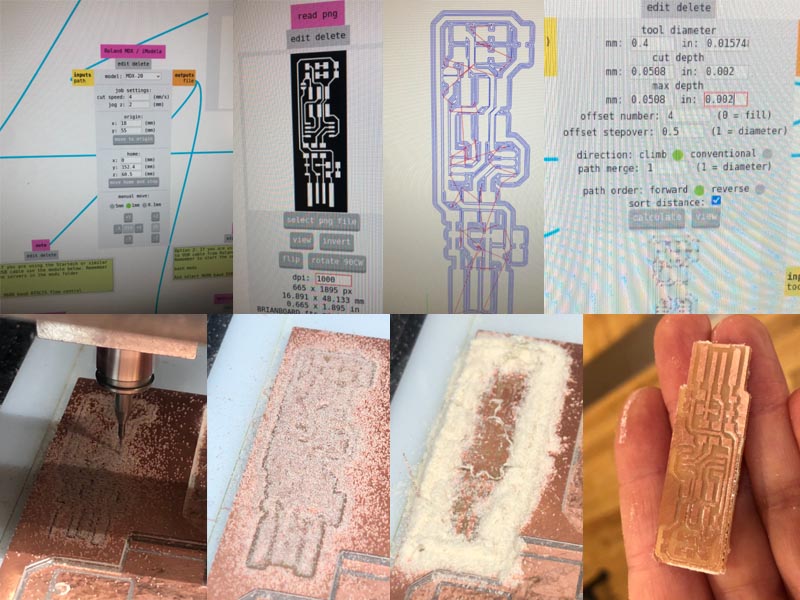
Milling and soldering
- First time failed because I didn’t put resolution as 1000 DPI so it ended up being a mess. Second time went smoothly. In the meantime I changed my code slightly because I added some neopixels at the start of the strip, which meant that I had to change all of my arrays. Luckily I added 10 neopixels so changing the numbers was easy.
Programming the ATtiny84
I’ve never programmed with a ISP programmer before, so I need to figure out how to do that first. My windows computer is also not great with discovering my programmer to begin with so I’ll just have to see as I go.
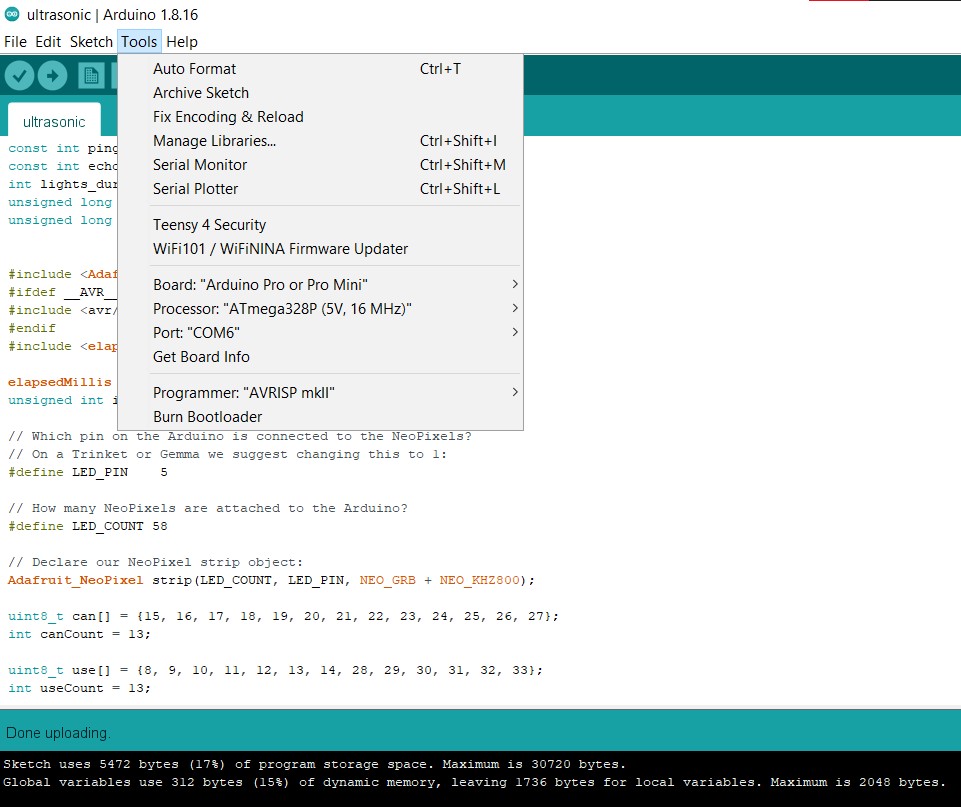
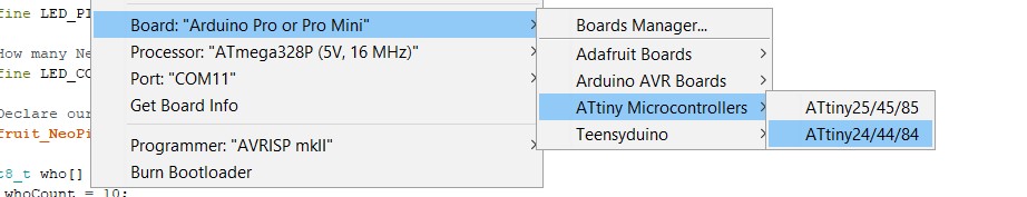
First I have to download the correct boards to ATTiny in the Arduino IDE: Preferences > Additional Boards Manager URLs and paste https://raw.githubusercontent.com/damellis/attiny/ide-1.6.x-boards-manager/package_damellis_attiny_index.json. Then go to Tools > Board > Boards Manager and type attiny, then install. You can then select the correct attiny from the boards list. I selected the ATtiny84 with an internal 8MHz clock because I found that value in the datasheet. Set programmer to USBtinyISP.
First error: “Serial was not declared in this scope” Serial like this doesn’t exist on the attiny84/85, so I need to use the correct equivalent which is SoftwareSerial or not use it at all. I decided to just get rid of it because I don’t need it for my actual board.
Second error: avrdude: initialization failed, rc=-1 Double check connections and try again, or use -F to override this check.

Henk told me to check my circuits for shorts, which I found; something went wrong with milling, causing my vcc and ground to be connected in the corner; and the big capacitor I accidentally over-soldered the vcc side to the ground as well.
http://fab.cba.mit.edu/classes/863.18/Harvard/people/david/week7_programming.html
5 volt adapter amperage needs:
To estimate power supply needs, multiply the number of pixels by 20, then divide the result by 1,000 for the “rule of thumb” power supply rating in Amps. Or use 60 (instead of 20) if you want to guarantee an absolute margin of safety for all situations. For example:
60 NeoPixels × 20 mA ÷ 1,000 = 1.2 Amps minimum 60 NeoPixels × 60 mA ÷ 1,000 = 3.6 Amps minimum
Internal clock: http://highlowtech.org/?p=1695
Notes on programming the attiny84
- kept getting the error ‘initialization failed, check connections’, so I couldn’t program the board; I kept checking my connections but everything was fine, but of course in the end it was my connections.
- after that I could program the board with my programmer, but now my board that was soldered and checked thoroughly again still didn’t work; the chip was programmed with the program and with a regular strandtest but nothing worked (except that sometimes the first neopixel would light up green)
- I replaced the power adapter, removed the neopixel capacitor (the electrolyted one), removed the ultrasonic sensor again, replaced the 470 ohm resistor with a 390 ohm one (and checked connection after every move), but it didn’t help
-
Then I added a regular LED (with some wires hanging around) and uploaded the blink test, which did work just fine, also with the power supply, so the problem isn’t that
- https://www.avrfreaks.net/forum/help-controlling-neopixel-ws2812b-attiny84
adding a 16mhz crystal oscillator IT WORKS FINALLY SO THAT WAS THE ISSUE
Then the next problem was that the neopixels would just all turn on bright white no matter the input; when connected to the power supply at least it would be less bright and only the selected neopixels would turn on (so if I said there were 60 instead of 68 they turn all on connected to my programmer, but when only powered by my power supply of 5 volt it would be fine). I found online (https://blog.adafruit.com/2016/10/28/tips-for-troubleshooting-neopixel-glitches/) that it’s probably because my power supply is too close to 4,7V (even higher) and my chip works better with 3.3V (but it’s 5.5V tolerant). However this wasn’t the issue according to Henk and it didn’t really make a lot of sense anyway since I hadn’t had issues with the previous Neopixel project like this. A bit more googling brought me to this stackexchange answer which turned out to be exactly what I was looking for. All I had to do was burn bootloader again with the new clock speed of 16Mhz and then upload. Then it works as expected!