Fabacademy: Fusion360
- Parametric: there is a workflow and timeline, the software updates in relation to one feature that you update so you can go ‘back in time’
- Cloud based: you can share folders with teams, exporting is not via computer but via cloud
Screen
- Orbiting with cube in top right corner (if you don’t have a mouse)
- Timeline at the bottom
- Browser: organization of all of the objects you create > keep the folders collapsed so you can keep track of what you are creating
- Data panel: all of your projects (in there: data with all versions), libraries and samples
- Create a folder per project for better overview, when collaborating you can invite people to the project in the People tab
Basic steps
- Create sketch
- Press R: create two-point rectangle (two opposite points); Esc when you’re done with rectangles
- Finish sketch
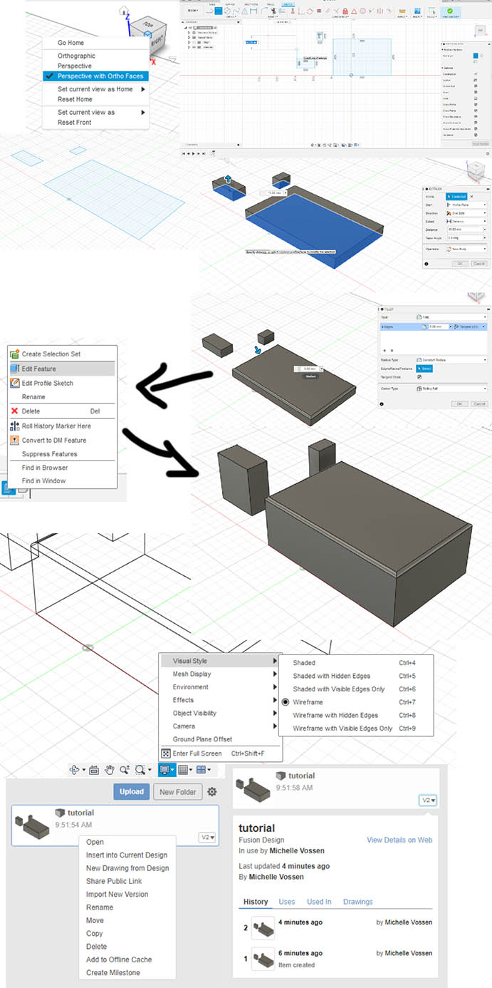
- Press E: extrude, select sketches and specify height you want, the output (new body in this case) and press ok
- Press F: fillet, select edges and specify radius etc. and press ok
- Right click feature in the ‘past’ and click edit feature; see how it affects the ‘future’. Notice how with every change a feature is added to the timeline; use the line on the right to go back in time
- Save (ctrl + s): every time you save your project you can add a version description. After saving the name is updated to the next version (v1>v2>etc). You can go back to every saved version in the data panel.
Constraints
Features we apply to our entities
- Horizontal/vertical: selected line becomes horizontal or vertical to the grid (depending on angle)
- Coincident: click two endpoints to connect them
- Parallel: click two lines to make them parallel to each other (first one is used as the reference)
- Midpoint: click a point, then click the line you want to use the midpoint of and the sketch object will move there
- Equal: click a shape/line and then a second to make the second equal to the first
- Deleting a constraint: click it and press delete
- Check them all out in the dropdown menu (they make sense)
- Press X: create construction lines
Instead of just drawing the line/shape you can also click and then enter values in the prompts (mm/deg/etc); press tab to go to the next value. This will fix the values. Fusion likes to create relations/constraints between shapes. If not wanted you can just delete them but they are very convenient.
Examples
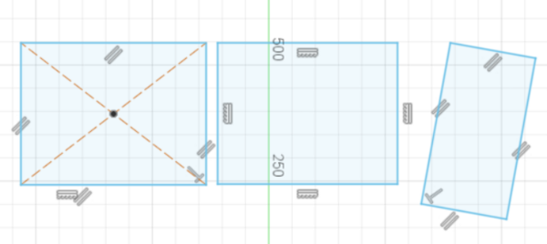
When creating a for example a center rectangle you can see that the constraints are different (left to right: center rect, 2 point rect and 3 point rect)
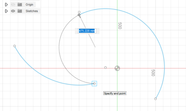
Center point arc is an arc based on a circle circumference (left), 3 point arc is created by first selecting start and end point and then a third point the arc goes through (right) and tangent arc (center) is a “halo that touches a circular halo” (just look at the image below).
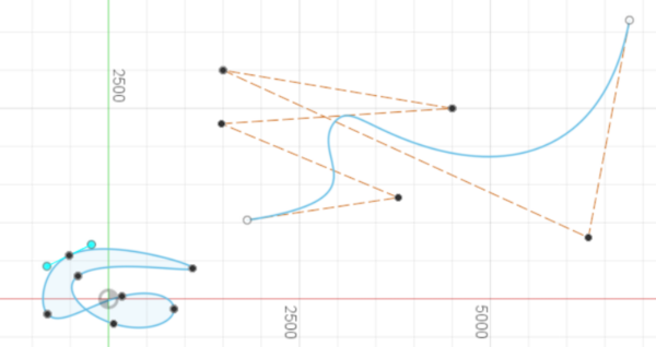
A fit point spline is a bezier curve (think of Illustrator), press escape to finish; then you can change the shape with the handles (left). Use control point spline to create a spline with construction lines.
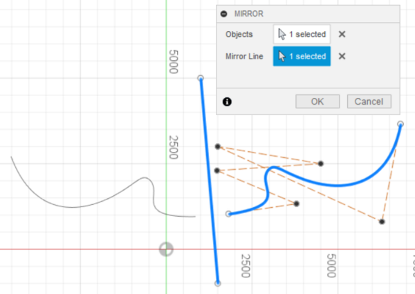
Mirror speaks for itself:
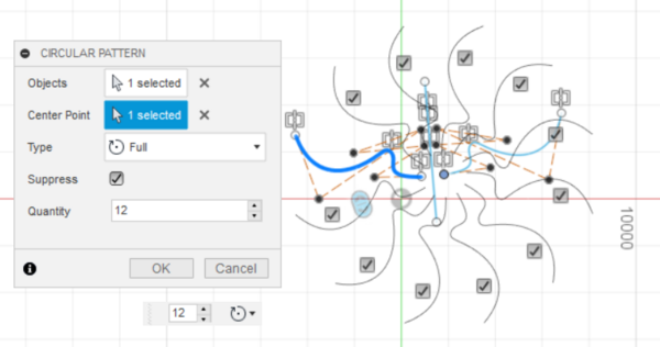
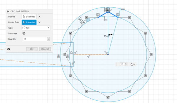
Circular pattern (use the blue slider to create more or less copies or enter a number): select the object(s) (or features etc.) and centerpoint to repeat the object around.
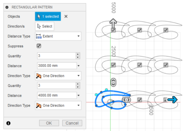
Rectangular pattern (is pretty intuitive):
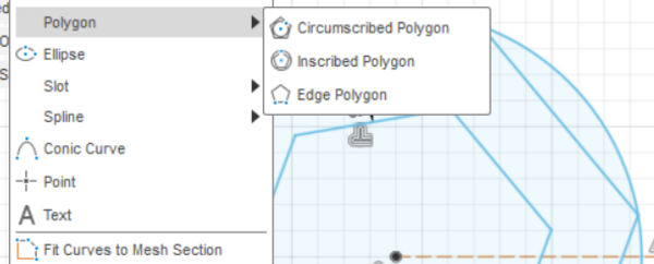
Polygons:
Workflow
- Look at basic shapes/geometries as a starting point (circles, rectangles)
- Not what but when is the most important question to ask yourself, the order of what you do has a very big influence on your workflow
- What you do in a sketch is not part of your timeline
- If something is not working as expected check if there are any unintentional constraints
Solid
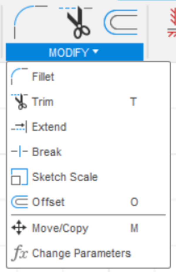
Example of impact of design decisions: if you want to extend the curve of an offset (shortcut for offset is O, found in the modify menu, left image below) the relation will be lost because the curves are no longer the same size (but you can move them around freely); sometimes you need that to get to your design but the parametricity will be lost. If you want to keep the parametricity you have to create a new line/shape/whatever, see the image below. Fusion helps you a great deal by suggesting constraints (like the parallel constraint below) but you can also add them manually in the menu.
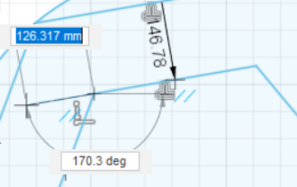
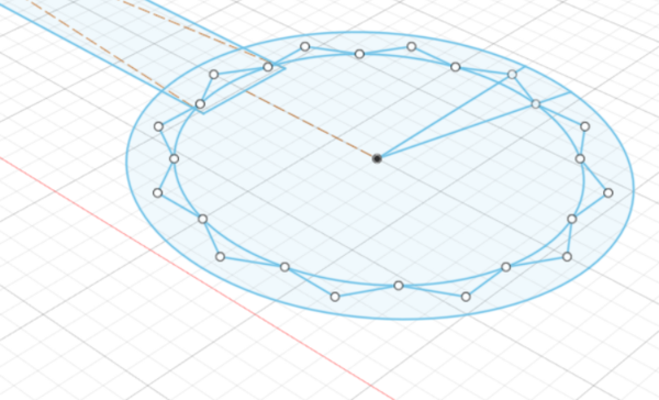
Shortcut for dimensions is D, very important for dimensions of and between sketch objects. On the image on the left the dimensions are set, the line from the center to the circumference is split using break and then a line is drawn from the corner right to the midpoint of the smaller line, which is then mirrored and repeated using a circular pattern. The finished sketch on the right.
When the sketch is finished, the menu shows different tools suited for 3D modeling (solid objects instead of sketch objects).
Plane: what you can create a sketch on (XY, XZ, YZ), can also be faces of what you already made > planar face Profile: selected geometric entity Surface: a geometric entity, a body without the 3rd dimension: it can be drawn in 3 dimensions but it has no thickness so it is 2D.
Important shortcuts
- S: pop-up searchbar for design shortcuts
- Ctrl + 4/5/6/7/8/9 for different visual styles
- D: dimensions (sketch)
- E: extrude, operations:
join cut intersect new body new component
- Chamfer: bevel, like a fillet but without the curve
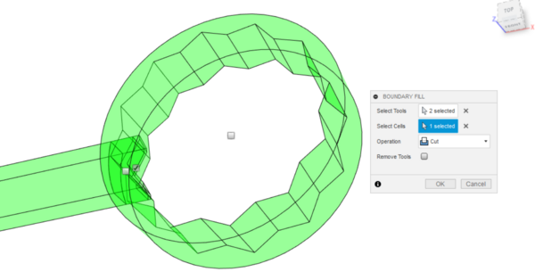
- Boundary fill: takes workplanes, surfaces and and solids as inputs. It intersects these shapes and finds all the closed volumes or “cells.” You can choose which cells you want and what type of operation you want them to perform.
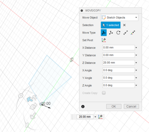
A 3d manipulation of a 2d sketch:
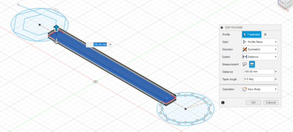
Wrench
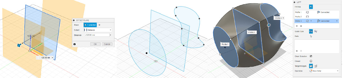
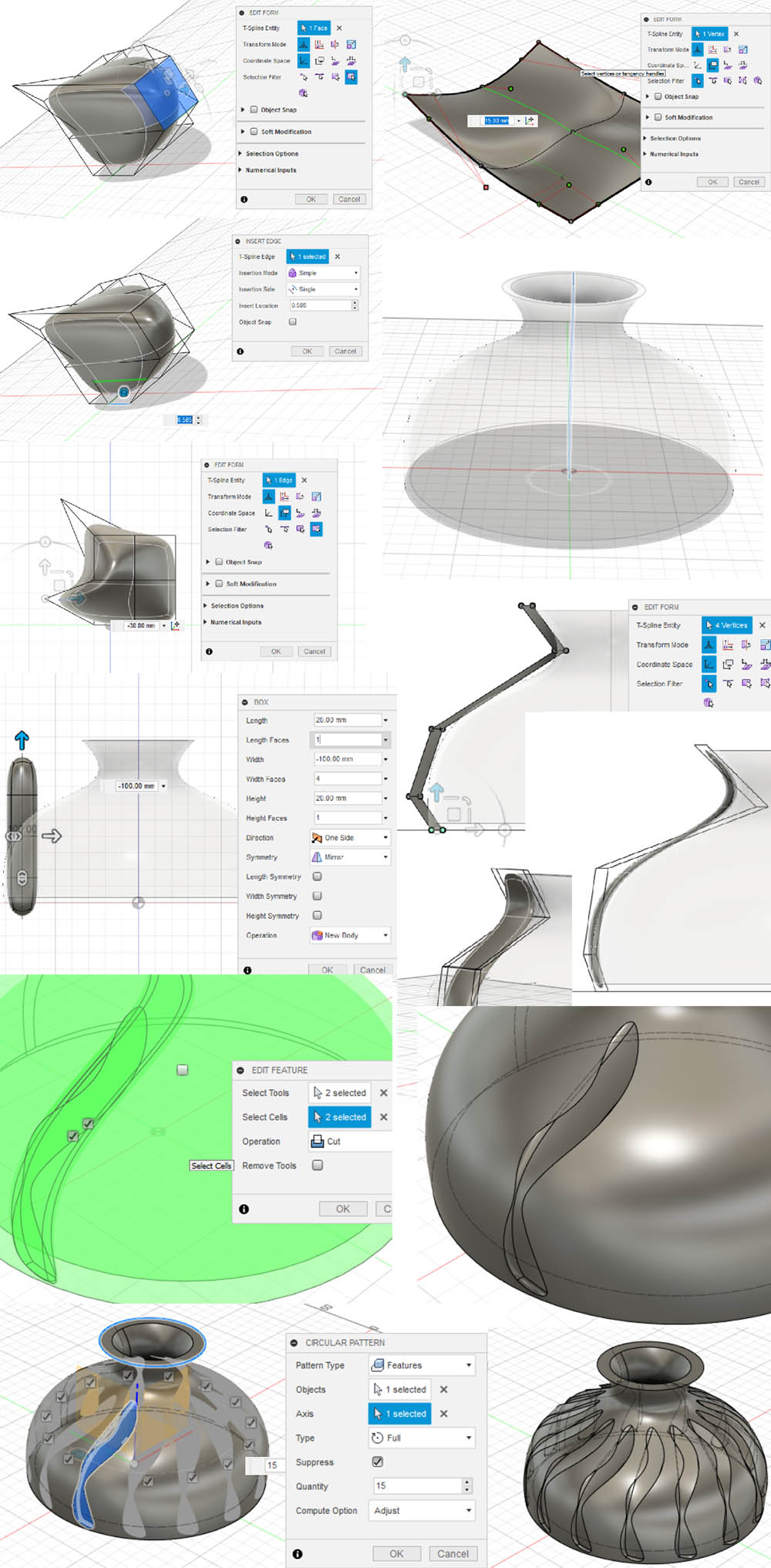
Vase
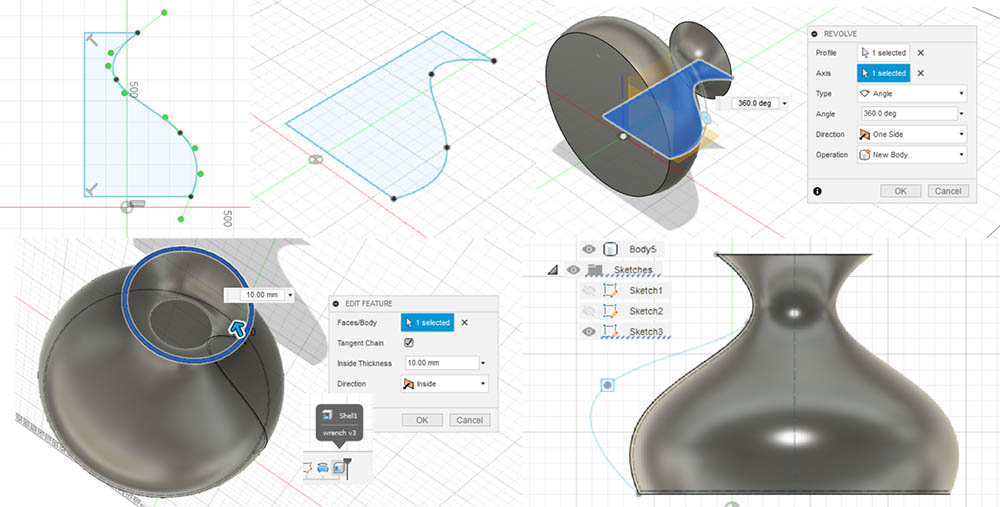
Loft: a way of connecting surfaces, making a shape of sketches. Start with a sketch, then make offset planes (construct menu) and make sketches on those planes. Then select loft from the create menu and click on the surfacesx.
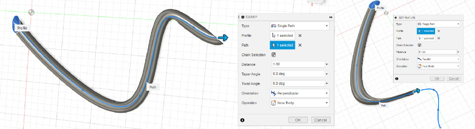
Sweep: make sure the path and profile intersect. The body is a projection of the sketch.
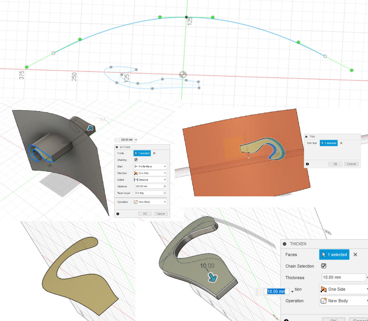
Surface
Different tab, different menu; now we’re working with hollow objects. Patch and stitch are very important for closing objects and making them solid.
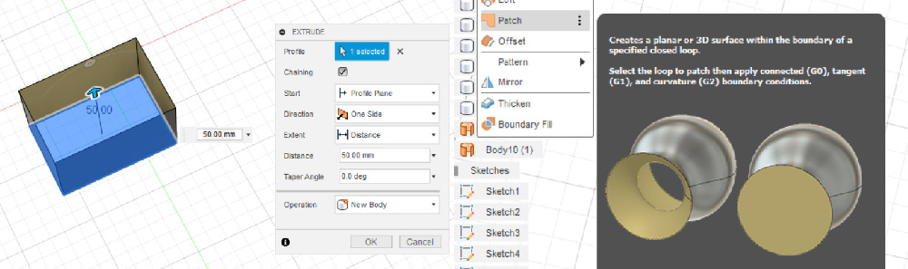
Extrude for surfaces is different than extrude for solids! Once you thicken a surface, it becomes a solid body. You can see this change in the browser. If you then want to add fillets, you have to go back to the solid menu.
Form
- Alt + 1/2/3 to change views
- Really work step by step to keep control > i.e. insert edge, then edit form and repeat. This can be found under modify. Start with as few lines as possible and add as you need them.
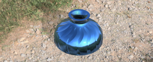
Render
Beautiful realistic render:
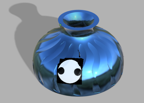
Adding an image (or logo) with decal:
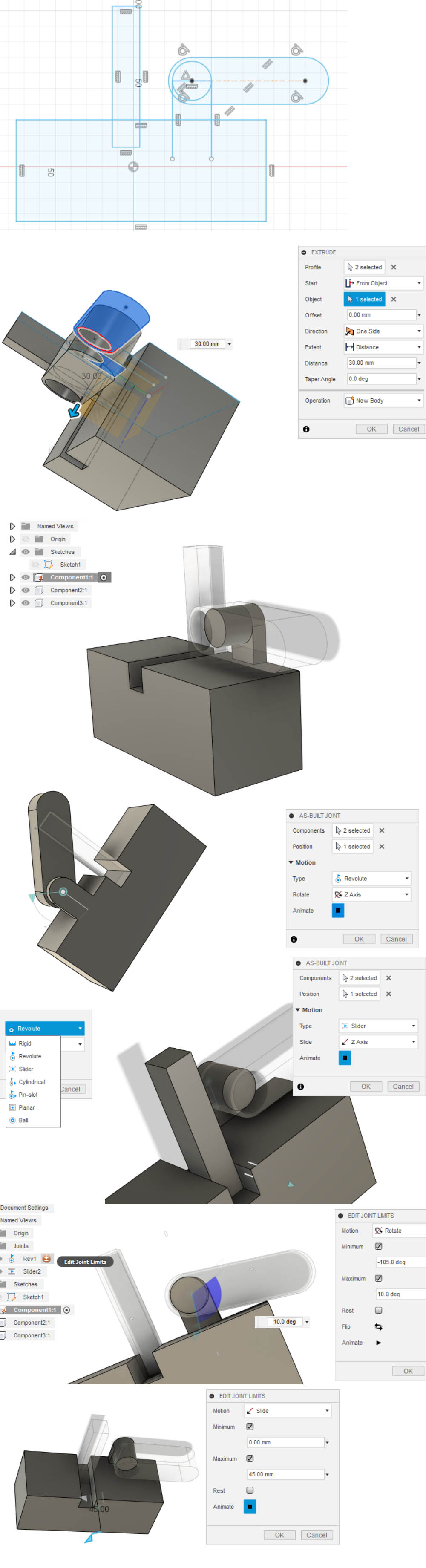
Mechanics
For this you need to transform your bodies into components (do this in the browser). Ground your base component (right click component and then ground, this will add a little pin to the component).
Assemble: as-built joint. Select the two components and the type of motion. In the folder joints you can set the limits. Contact all: so they can’t move through each other Motion link: when one component moves, another moves as well
Animation
Drawing
Other notes
You should try other programs too depending on your goals, like:
- AutoCad: perfect for architecture, buildings
- Rhino: works on surfaces (not bodies, so not great for 3d printing) (“house made of cards”)
- FreeCad: linux, open source
- Solidworks
- CAD/CAM: Computer Aided Design/Manufacturing