Back to overview
Electronics design notes
Assignment: design a board, make it and test it, programming it in 2 weeks (add button, LED, add a few components). You can use existing code to test the communication. To go straight to the KiCad documentation, click here.
Crash course into components
Wire
- Ribbon cable: when you need a multi conductor cable and connectors that clip onto it; and we use it as hook-up wire (peel it off)
- Awg (american wire gauge) wire current tables for information on your wires (diameter, resistance, current etc)
- You need a wire that is thick enough for the current you’re carrying, otherwise it will overheat
- Wire with solid core (low frequency) and wire with strands (high frequency)
Button
- Push button: when not pressed it’s open, it closes the circuit when pushed (2 legs on opposing sides)
- Slide switch: stays where you leave it (open or closed), center conductor and 3 side conductors (used for on/off buttons often)
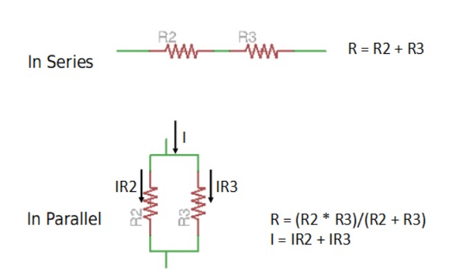
- Resistor: specified by a resistance value (I = V / R). There is a current flowing through the resistor > there’s voltage drop across the resistor, and the change in voltage equals current * value of the resistor (they have max. power that they can take before overheating, and tolerance for errors). We use resistors to control current (current limiting) most commonly, or for timing
Capacitor
- Capacitance (C = Q / V, V). There is charge on it; it stores charge, there is an electric field in it. The rate of change of the charge equals the current (Current is proportional to the rate of change of voltage for a capacitor). Vdot proportional to I
- If the voltage is constant/steady, nothing goes through, but if the voltage changes quickly, something comes through > AC goes through, DC is blocked
- Farad is the unit, max. voltage is important to note
- There is polarized (bit more complex, stores energy and can be used as an energy source to quickly charge for example a toy) and unpolarized capacitors (unpolarized are the ones we use)
- A capacitor ‘cleans up’ noise in the voltage between power and ground
- A bigger capacitor near your component stores a little bit of energy (acts as a battery) when you switch it on
Crystals and resonators
- A capacitor with a material on the inside, with voltage on it it flexes, like pushing a swing (oscillating)
- Can be used to tell time
- Unit is frequency
- Internal clocks in processors are now good enough to use for most purposes, only need to use them if timing is very precise
- Resonators are cheaper
Inductors
- V = L * Idot
- DC goes through, AC is blocked
- Blocks high frequency noise
- Inductors and capacitors can oscillate together, for filters or interfacing radios
- Less used compared to other components
Diode
- 2 sides, anode and cathode, a > c
- Can use it to block a signal (or stop you from frying your board if you connect it the wrong way I think)
- Diode drop > prevents current from going backward
- In the forward direction: past the diode drop it’s essentially a perfect conductor
- The dent/dot/etc is always the cathode side
- You can use a Zener diode to clamp a voltage (when you don’t want it to go above a certain voltage)
- LED is a diode (always check the spec sheets for brightness, color, max voltage etc, you need a resistor for this weeks assignment, typically 1kOhm otherwise you could literally blow up the LED)
Mosfet (transistor)
- Gate, drain and source
- Parameters we care about: max. current it can handle, rbs (resistance between drain and source, you can look at the graphs for this)
- You can loosely think of this as a switch (it’s actually continuous), as you vary the gate voltage, the gate is controlling the value of the resistance between source and drain; generally all the way on or off and then turns on and off quickly (with intermediate values you dissipate power > HEAT)
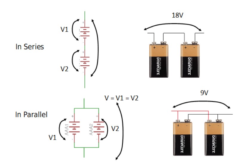
Power supply
- Batteries or
- You need regulators to work with the processors (to go from X Volt to for example 5 Volt). You need a difference to regulate! Otherwise the regulator doesn’t have anything to regulate. You always need the output one
Op-amp
- Output is (input * output) * huge multiplier (a million or something), to amplify a signal
- Spectacular specs
- Neil loves them
- Microcontrollers we use have them built right into them so we usually don’t need a separate one
- You could use them to interface to a microphone, or if you need very sensitive filters (you could also make software filters if it’s not that sensitive)
Microcontroller
- Basically a small computer
- Example of integrated circuits (all the components are hidden inside)
- Designed to perform a predefined task (you give input, the controller gives an output) that you program it to do. It has no working memory so you can’t store anything on it, and there’s no operating system on it.
- You need to understand the datasheets!!! Read them, there’s so much going on in a 1 dollar piece, it’s amazing
Designing circuits
- Kirchoff’s law: all your voltage going in has to go out (total is 0 unless you’re charging something)
- Power = I^2 * R = I * V
- Wherever possible we want voltage drop to be low and resistance to be low (less heat)
- EDA: electronic design automation
- Designing PCB’s needs to be hierarchical and parametric (because of trace size, package size etc)
- Footprints: the bits where you connect the components; they come from part libraries
- Processor: dot goes on the little longer footprint to help with the orientation
- Routing the traces (autotraces don’t always work for small circuits)
- Simulate before you make it
- Your design has to respect your machine’s design rules
- You can also draw one by hand (nice to try out, not recommended)
- Rat’s nest: not routed yet
PCB Design Tools
- Fritzing, TinkerCad, Virtual Breadboard: nice for learning but we’re not going to use them
- LibreCad, EasyEDA: options, open source
- Eagle: also good option, great integration with Fusion360, however it’s not free and open source, but it’s integrated in Fusion360 license
- KiCad (free, open source and cross platform): we are using this one
- OrCad, Cadence (1 million dollars to set up the installation), Synopsis: higher end PCB design
- Magic is an open source tool also with integrated circuits
Kicad
- Very powerful
- A bunch of separate programs so that makes it harder to go back and change something
- Wire up the resistor to the processor
- Open the tool and tell the value of the resistor and which package for the processor we use
- Produce net list: who is connected to whom
- Open PCB tool, bring in net list
- Start routing (takes quite some time): connect the components (push routing: helps with routing)
- Edge cut: defining the boudary of the board (there’s a 3d viewer in KiCad)
- Export layers (multiple formats available): we export images for mods (SVG, white is high and dark is low, so we have to invert the svg)
- Mill it
Libraries
- Logical representation of components in libraries
- Vendors want you to use their parts so they work on great library sources
- Chris’s library for KiCad is current and great
Simulators
- There’s very expensive high end simulators for very expensive chips
-
Fahstad.com in browser simulation is really cool
- Verilog: hardware description languages, expressing algoritmic relationships (not recommended for beginners)
- PCB.py: functional representation
Digital oscilloscope: logic analyzer, great tool for debugging, 300 dollar, looking at signals